Moon phase display device, particularly for a timepiece

a technology for displaying devices and moon phases, which is applied in the field of moon phase display devices, can solve problems such as drawbacks, inability to always avoid the appearance of a line break, and relatively bulky devices in plan

Active Publication Date: 2005-04-26
THE SWATCH GRP RES & DEVELONMENT LTD
View PDF8 Cites 12 Cited by
  • Summary
  • Abstract
  • Description
  • Claims
  • Application Information

AI Technical Summary

Benefits of technology

[0007]The present invention concerns a device for displaying the phases of the moon largely avoiding the drawbacks of the prior art and showing, in a circular aperture, an i

Problems solved by technology

Such a device is relatively bulky in plane.
At the phases where the separation line is formed by a combination of the dark zones of the two discs, one cannot always avoid the appearance of a break in said line at the place where the edges of the two dark zones intersect.
Moreover, the image of the moon can only be formed in one p

Method used


Image

  • Moon phase display device, particularly for a timepiece
  • Moon phase display device, particularly for a timepiece
  • Moon phase display device, particularly for a timepiece

Examples


Embodiment Construction

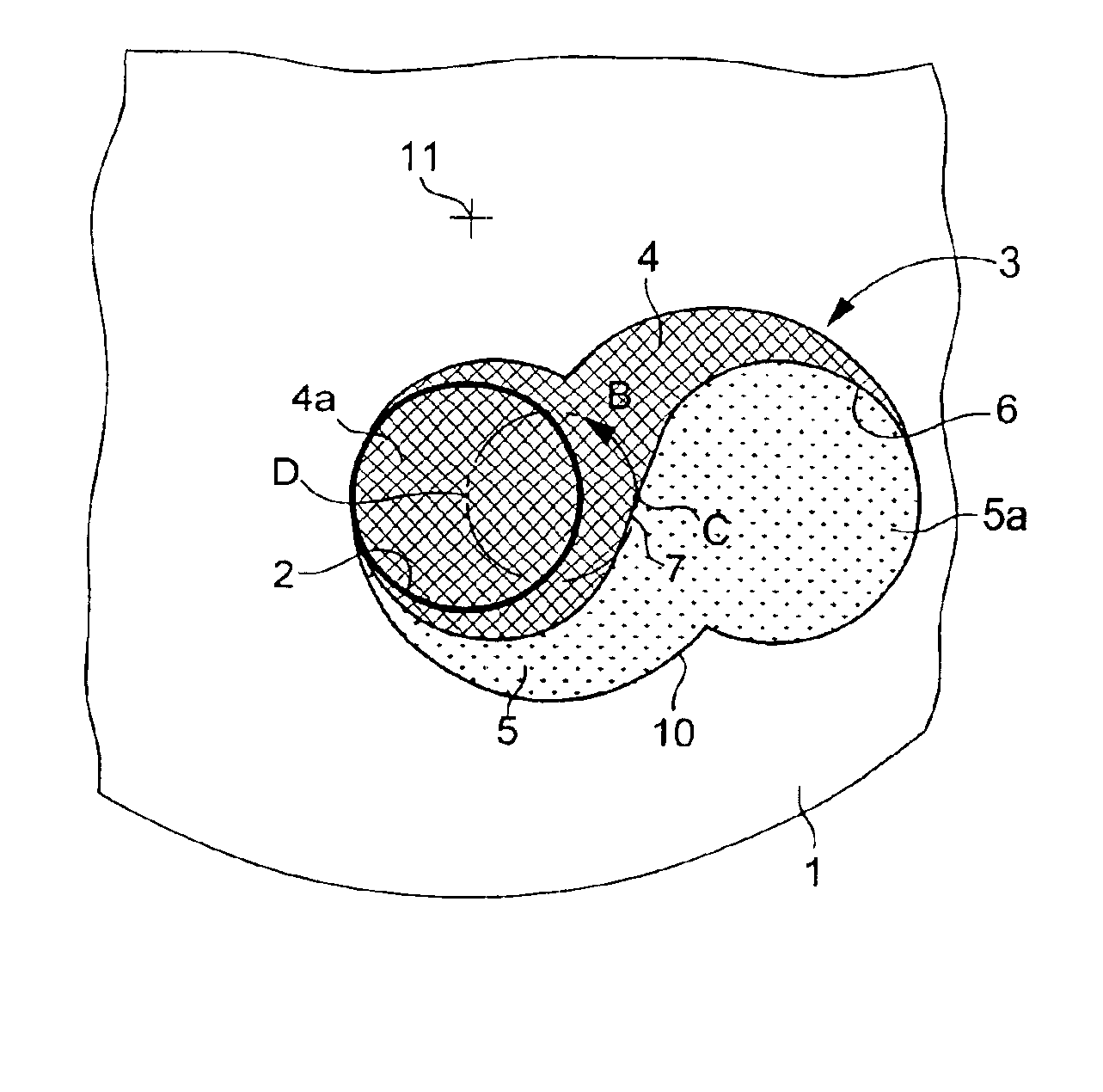
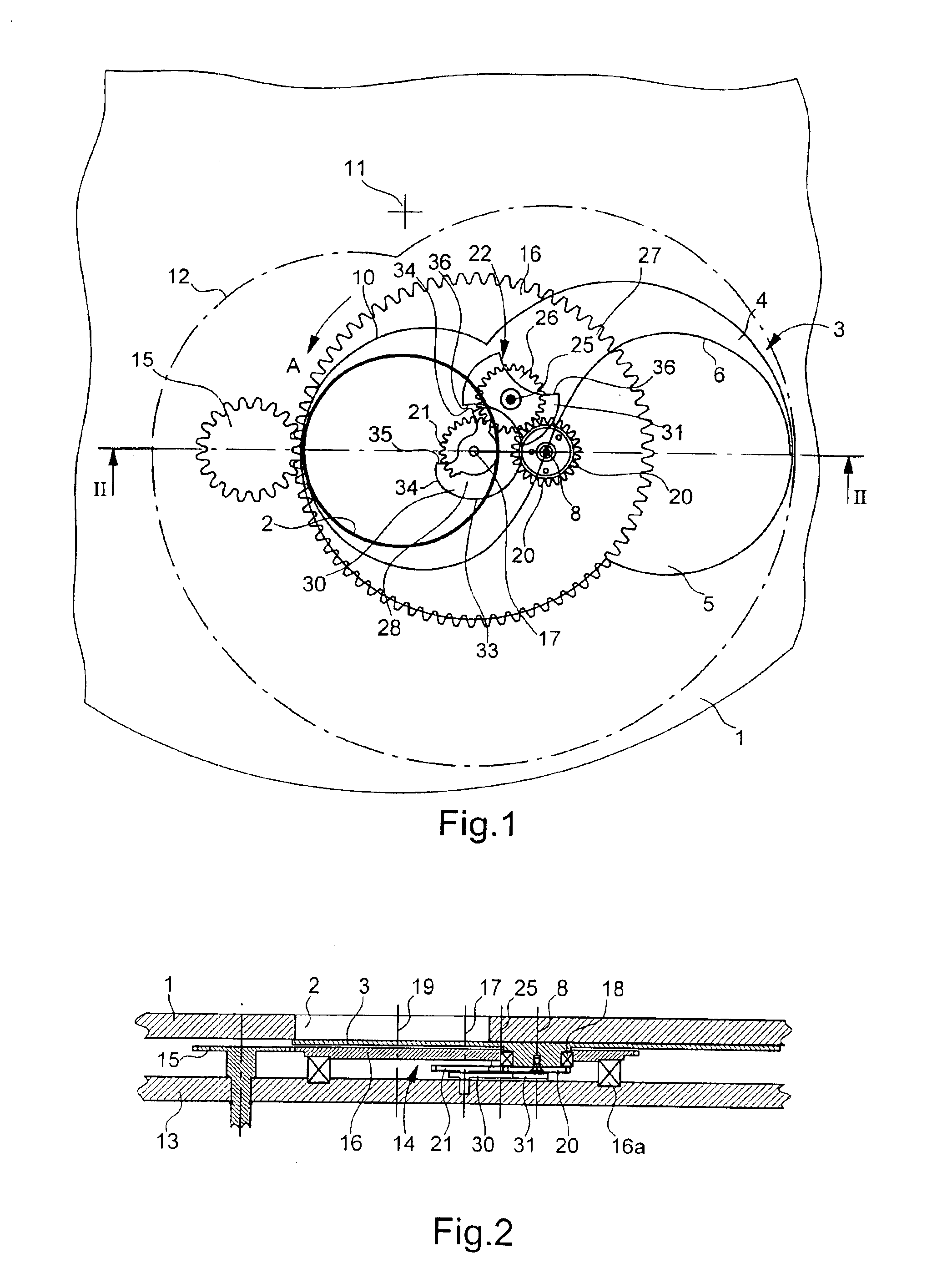
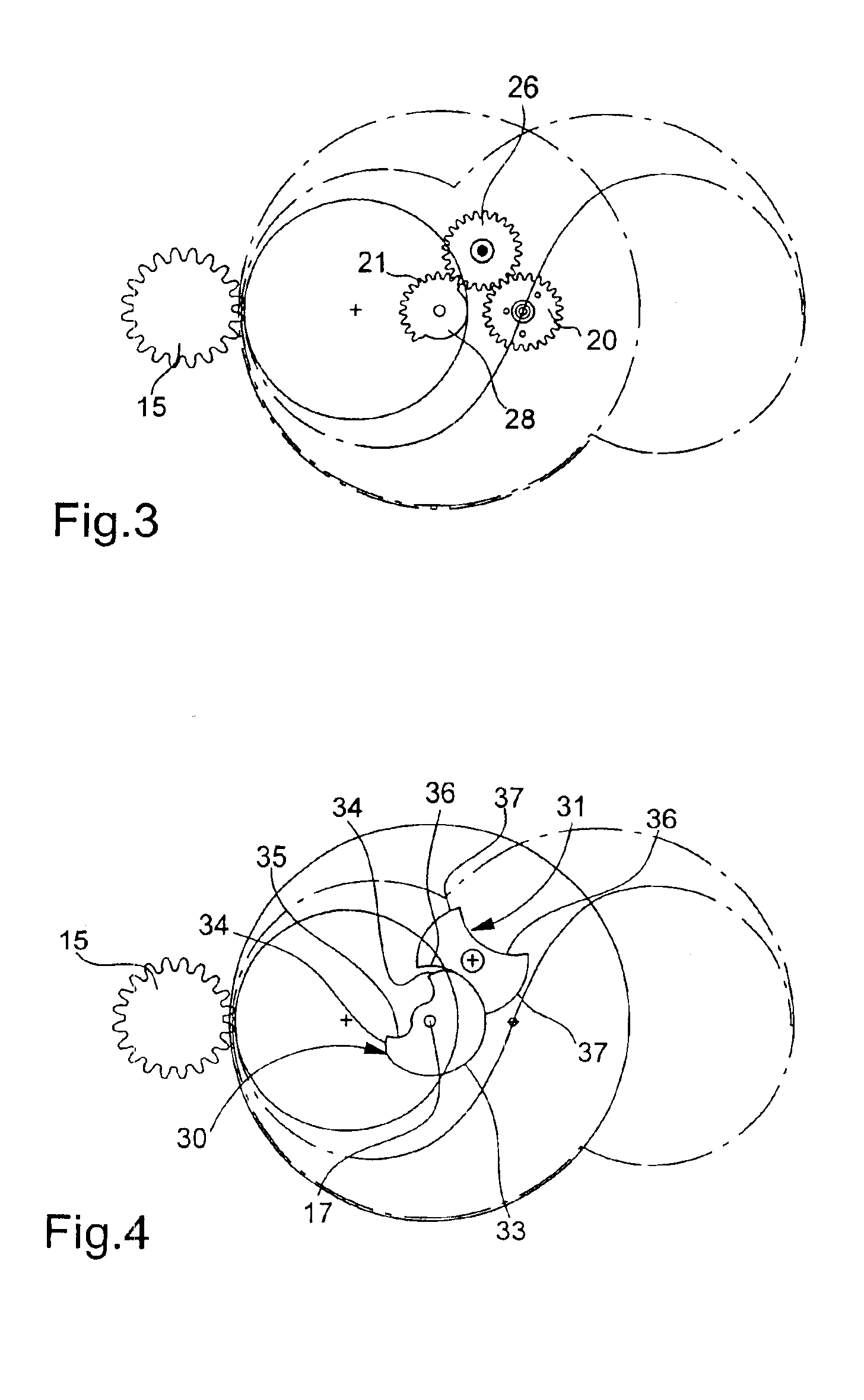
[0020]With reference to FIGS. 1 to 4, the moon phase display device includes a dial 1, which can be the dial of a watch in which the device is fitted, this dial having a circular aperture 2 through which the observer can see a mobile indicator 3 in the shape of a plate, which moves in its own plane just behind dial 1. The upper surface of indicator 3 is subdivided into a dark zone 4 and a light zone 5 which are separated from each other by an approximately S-shaped sinuous line 6, as can be seen more clearly in FIG. 5. The line of separation 6 has rotational symmetry with respect to its central point of inflexion C. Point C coincides with a axis of pivoting 8 of indicator 3. Preferably, dark zone 4 is black and light zone 5 is the yellow colour usually used in s displays of the phases of the moon, but other colours can be used. The terms “dark” and “light” employed here to qualify zones 4 and 5 of the indicator have only a relative value and should not be interpreted as qualifying s...


PUM


Abstract

The device includes an indicator (3) in the shape of a plate, moving behind a dial (1) having a circular aperture (2), which represents the lunar disc. The indicator includes an S-shaped line of separation (6) between a dark zone (4) and a light zone (5) representing the non-illuminated part and the illuminated part of the moon in the aperture. The indicator is rotatably mounted at the centre of symmetry C of the line of separation (6) on a rotating support making two revolutions per lunation. An image matching the appearance of the moon in each phase is thus obtained. Such a device can be used particularly in a watch or another timepiece.

Description

[0001]This application claims priority from European Patent Application No 03010126.5 filed May 5, 2003, the entire disclosure of which is incorporated herein by reference.TECHNICAL FIELD[0002]The present invention concerns a device for displaying the phases of the moon, particularly in a watch or other timepiece, including a dial provided with a circular aperture, a mobile indicator in the shape of a plate, moving behind the dial and having a substantially S-shaped separation line between a dark zone and a light zone which can be seen through the aperture, the indicator having a pivoting axis that passes through a centre of symmetry of the separation line, an entry element rotatably mounted on a plate and making a determined number of revolutions per lunation, and a transmission mechanism assuring a kinematic connection between the entry element and the indicator.BACKGROUND OF THE INVENTION[0003]In conventional moon phase display devices, a disc bearing two images of the full moon ...

Claims


Application Information

Patent Timeline
IPC IPC(8): G04B19/26G04B19/00
CPCG04B19/268
Inventor REY-MERMET, GILLES
Owner THE SWATCH GRP RES & DEVELONMENT LTD
Why Eureka
Try Eureka