Rate adaptive pacemaker

a pacemaker and adaptive technology, applied in the field of rate adaptive pacemakers, can solve the problems of heart failure, and inability to meet the physiological needs of the patient's organism, and achieve the effect of avoiding the lack of oxygen supply to the myocardium and the excessive pacemaker

Inactive Publication Date: 2005-04-26
ST JUDE MEDICAL
View PDF14 Cites 6 Cited by
  • Summary
  • Abstract
  • Description
  • Claims
  • Application Information

AI Technical Summary

Benefits of technology

[0008]The above object is achieved in accordance with the principles of the present invention in a rate adaptive pacemaker having a measurement arrangement for determining a patient's demand, a pacing rate controller which controls the pacing rate in response to the patient's demand, and a pacing rate limiter which prevents the pacing rate from becoming too high. The pacing rate limiter limits the pacing rate upwardly so that a predetermined relation is maintained between the energy supplied to the myocardium and the energy consumed by the myocardium.
[0009]Thus, in the pacemaker according to the invention the myocardium energy consumption and energy supply can be kept in balance, and since this relation, and not the heart rate, is of primary importance, the patient can feel more healthy and comfortable in various everyday life conditions, also in conditions of active work. According to the invention the pacing rate limiter is adapted to limit the pacing rate upwardly such that the energy consumed by the myocardium always is less than the energy supplied to the myocardium. In this way lack of oxygen supply to the myocardium is avoided.

Problems solved by technology

This may cause lack of oxygen supply to the myocardium.
Thus, in certain conditions the heart may not be able to satisfy the physiological needs of the patient's organism and heart if the pacing rate is not limited.

Method used


Image

  • Rate adaptive pacemaker
  • Rate adaptive pacemaker
  • Rate adaptive pacemaker

Examples


Embodiment Construction

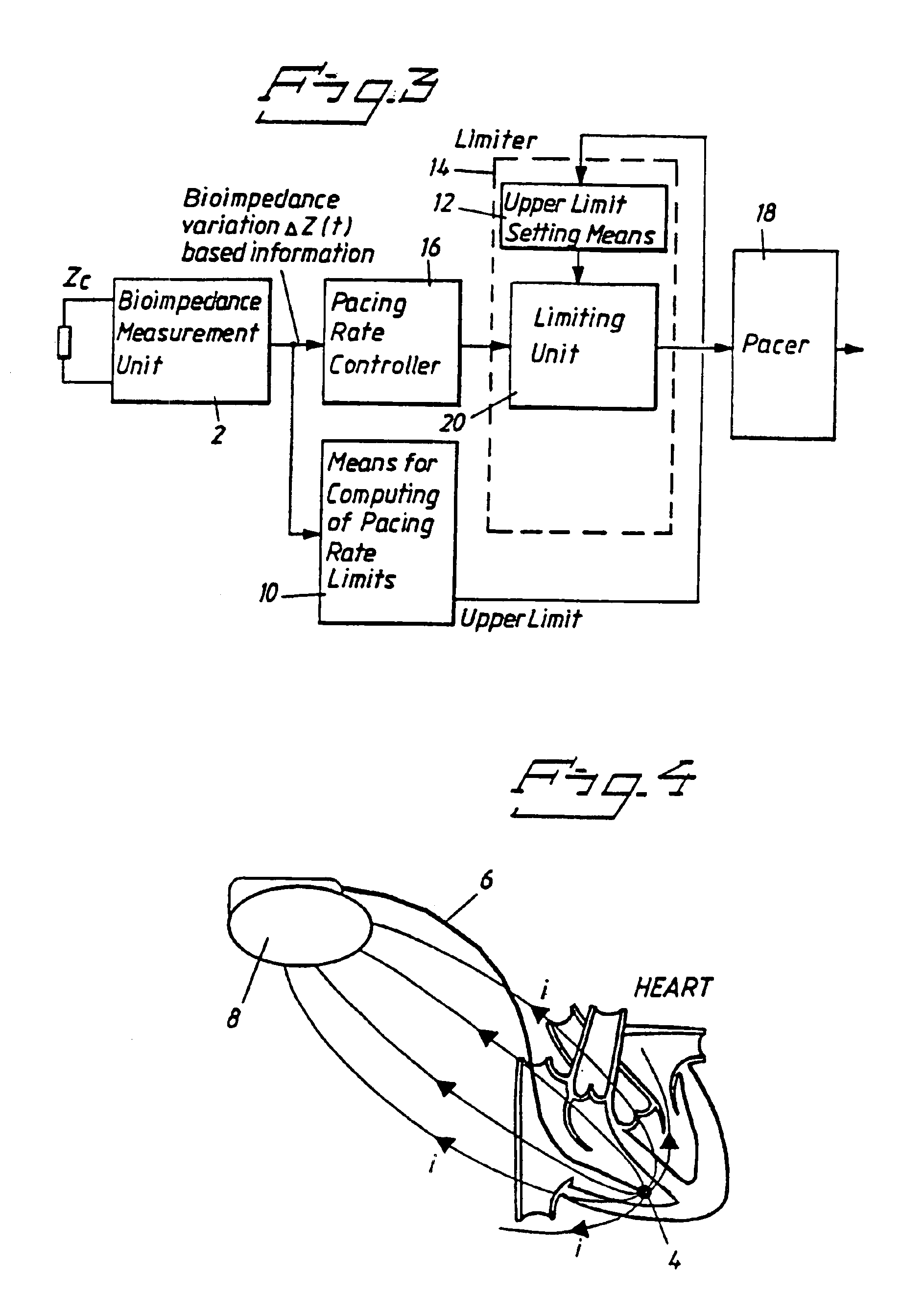
[0018]As mentioned above, according to one embodiment of the pacemaker according to the invention an upper limit value for the pacing rate is determined based on a balance between the energy consumption of the myocardium and the energy supplied to the myocardium for high patient workloads.

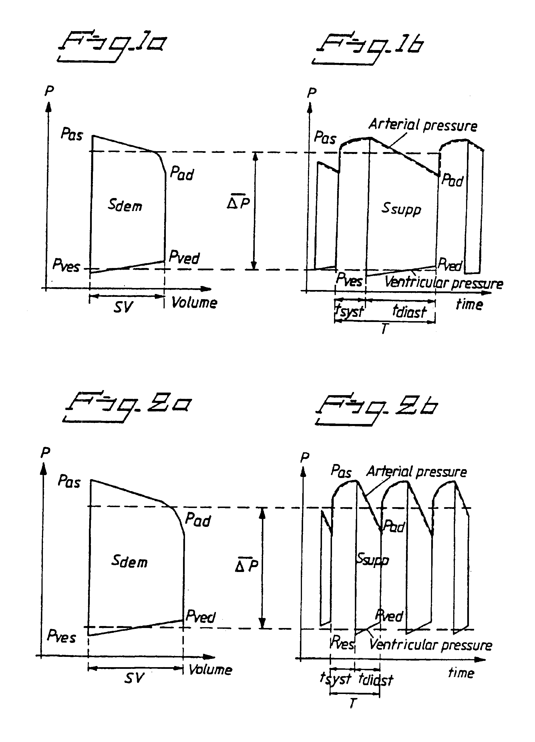
[0019]Since the oxygen demand, or demanded energy consumption which is equal to the work of myocardium, is well correlated to the area Sdem within the ventricular pressure-volume loop shown in FIG. 1a, the following equations are valid

W=Sdem={overscore (Δ)} {overscore (P)}×SV  (4)

where W denotes the work of the myocardium, {overscore (Δ)} {overscore (P)} the mean value of the ventricular pressure variations during a cardiac cycle, and SV the stroke volume.

[0020]Further, in FIGS. 1a, 1b and 2a, 2b, Pas denotes the atrial systolic pressure, Pves the ventricular systolic pressure, Pved the ventricular diastolic pressure and Pad the atrial diastolic pressure.

[0021]The energy supplied to the myocardium...


PUM


Abstract

A rate adaptive pacemaker has a measuring unit which interacts with a patient to determine a demand, a pacing rate controller connected to the measuring unit for controlling the pacing rate in response to the demand, and a pacing rate limiter connected to the pacing rate controller which upwardly limits the pacing rate so as to always maintain the energy supplied to the myocardium at a level which exceeds the energy consumed by the myocardium.

Description

BACKGROUND OF THE INVENTION[0001]1. Field of the Invention[0002]The present invention relates to a rate adaptive pacemaker of the type having circuitry for determining the demand of the patient's organism, a pacing rate controller for controlling the pacing rate in response to the patient's demands and a pacing rate limiter for preventing the pacing rate from becoming too high.[0003]2. Description of the Prior Art[0004]Pacing rates that are too high can appear in a rate adaptive pacemaker due to the physical demand of the patient's organism and heart. This may cause lack of oxygen supply to the myocardium. Thus, in certain conditions the heart may not be able to satisfy the physiological needs of the patient's organism and heart if the pacing rate is not limited.[0005]Several different proposals for upwardly limiting the pacing rate have been presented. Thus in e.g. U.S. Pat. No. 5,350,409 a rate adaptive pacemaker is described having an upper pacing limit programmed beyond which ra...

Claims


Application Information

Patent Timeline
Patent Type & Authority Patents(United States)
IPC IPC(8): A61N1/365
CPCA61N1/36521A61N1/36585A61N1/36564
Inventor MIN, MARTKINK, ANDRESPARVE, TOOMAS
Owner ST JUDE MEDICAL
Why Eureka
Try Eureka