
Electronic component and method for cooling

a technology of electronic components and cooling methods, applied in the direction of electrical equipment contruction details, lighting and heating equipment, etc., can solve the problems of equipment operating at excessively high temperatures, unable to cool or at least adequate cooling,

Pending Publication Date: 2019-12-19
EATON INTELLIGENT POWER LIMITED
View PDF9 Cites 1 Cited by
  • Summary
  • Abstract
  • Description
  • Claims
  • Application Information

AI Technical Summary

Benefits of technology

The patent text describes a safety switching apparatus that prevents a shortage of cooling fluid and helps to switch off equipment to prevent additional heat from being generated. The cooling fluid used should be suitable for the specific use of the equipment and should have a boiling point lower than the maximum allowed surface temperature of the equipment. Examples of suitable coolants include insulating oils, 3M Novec™, or even distilled water. 3M Novec™ is recommended because it has a wide range of boiling points and is not flammable, with excellent insulating properties.

Problems solved by technology

It has however been found that, with the cooling fluid supply apparatuses hitherto known from practice, cooling or at least adequate cooling is no longer possible, for example, in the case of a leak in the cooling fluid circuit, a high temperature inside the housing of the equipment and the ensuing evaporation of the coolant and the like.
In addition, equipment operating at excessively high temperatures can present a danger especially in potentially explosive areas.

Method used


Image

  • Electronic component and method for cooling
  • Electronic component and method for cooling

Examples


Embodiment Construction

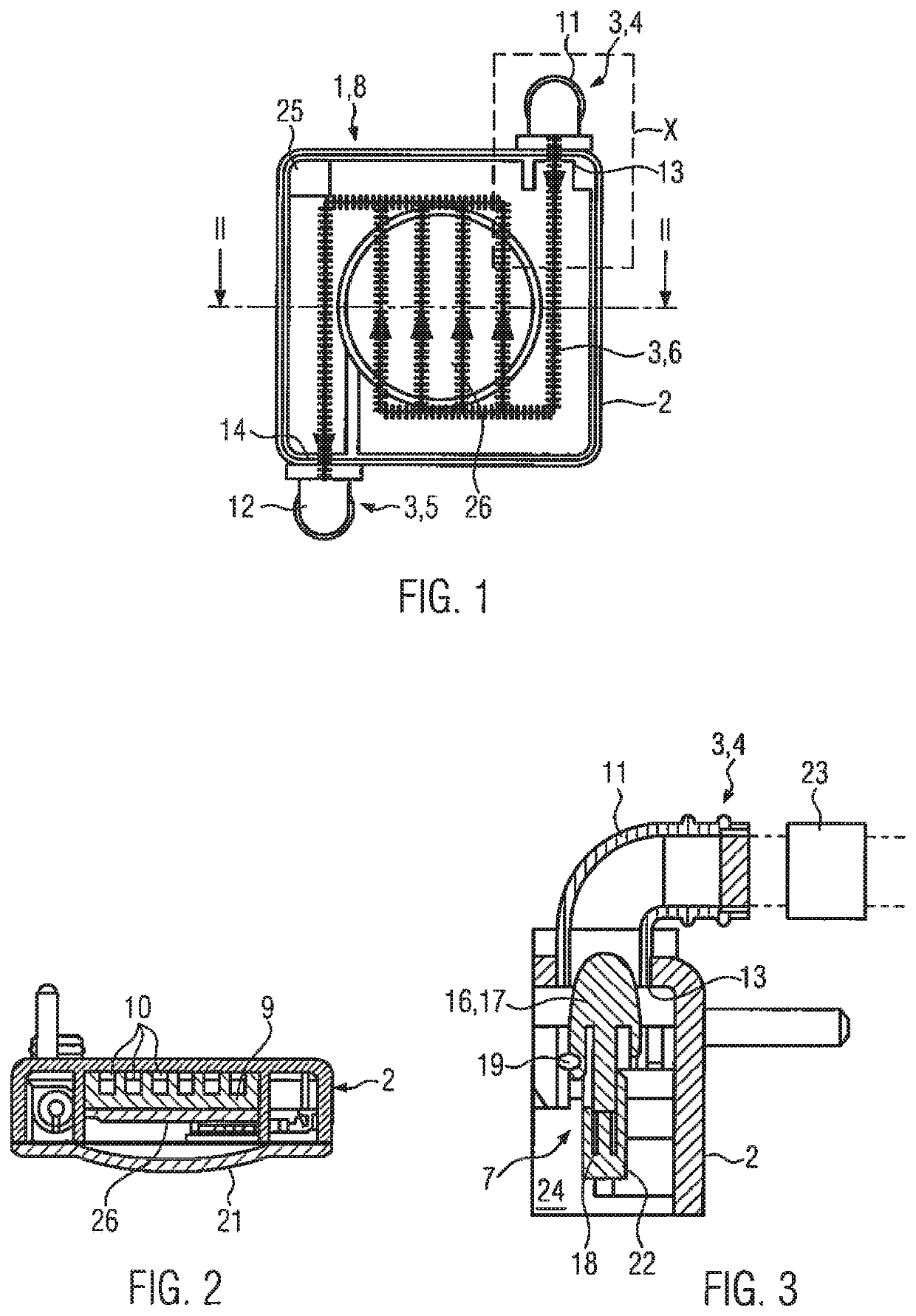
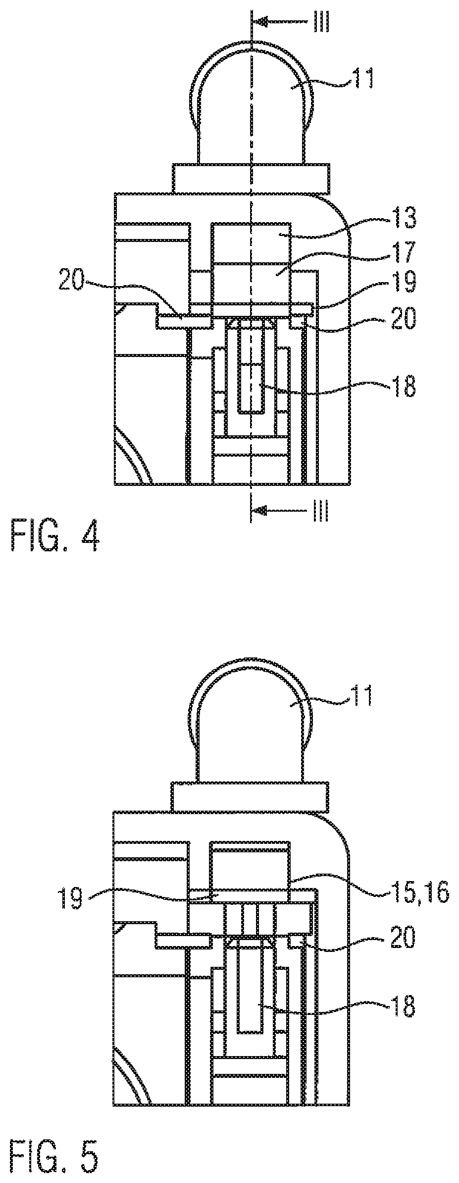
[0047]FIG. 1 shows a plan view of an item of electrical / electronic equipment 1 according to the invention. This equipment is a high-powered lamp 8 having at least one high-powered LED 26, hereinafter referred to as H-LED. The lamp has a housing 2 which, in the illustrated view, is essentially square, although other forms of housing are also possible. The H-LED 26 is arranged inside the housing. A cooling fluid supply apparatus 3 is allocated to the H-LED 26 and in particular also to the housing 2. Of the cooling fluid supply apparatus 3, only a cooling fluid inlet apparatus 4 and a cooling fluid discharge apparatus 5 are shown in the form of pipe sockets at diagonally opposite ends of the housing. The cooling fluid inlet apparatus and cooling fluid discharge apparatus are connected outside the housing to other housings and to the rest of the cooling fluid supply apparatus 3. The cooling fluid supply apparatus 3 may also have a heat exchanger 23; see FIG. 3.

[0048]Inside the housing, ...


PUM


Abstract

The invention relates to electrical / electronic equipment, such as a high-powered lamp, switching device, control device, transformer, signaling device, display device, or the like, having a housing (2) and at least one cooling fluid supply apparatus (3) arranged in the housing or allocated thereto. Said cooling fluid supply apparatus has a cooling fluid inlet apparatus and a cooling fluid discharge apparatus on the housing and a cooling fluid guide apparatus within the housing.In order to improve such equipment such that safe actuating of the equipment is possible, together with a compact and competitive design, with simultaneously efficient cooling, in particular also in potentially explosive areas, at least the cooling fluid inlet apparatus is allocated a safety switching apparatus for interrupting the cooling fluid supply, in particular in the case of a pressure drop in the cooling fluid. The invention also relates to a corresponding method.

Description

CROSS-REFERENCE TO RELATED APPLICATIONS[0001]This application is a National Stage Entry of, and claims priority to, PCT Patent Application No. PCT / EP2017 / 081219, filed Dec. 1, 2017, which claims priority to German Patent Application No. 102016224064.1, filed Dec. 2, 2016, both of which are hereby incorporated by reference in their entirety.FIELD OF THE DISCLOSURE[0002]The invention relates to electrical or electronic equipment, such as a high-powered lamp, switching device, control device, transformer, signaling device, display device, or the like.BACKGROUND[0003]Such equipment, like other compact electronic parts, generates heat which must be dissipated in order to prevent damage to the corresponding components and in particular also to increase the service life of the components. Additional requirements for such equipment, for instance, limiting the surface temperature or reliably controlling sparks in order to prevent an explosion, exist in explosion-protected areas.[0004]In othe...

Claims


Application Information

Patent Timeline
Patent Type & Authority Applications(United States)
IPC IPC(8): H05K5/02F21V29/56H05K7/20F21V25/12
CPCH05K7/20209H05K7/20327H05K5/0213F21V25/12F21V29/56H01L23/473H01L33/648H05K7/20272F21V29/52F21V29/83F21V29/58F21Y2115/10
Inventor SCHWARZ, BERND
Owner EATON INTELLIGENT POWER LIMITED
Learn More