Rotor clearance measurement gage

a technology of rotor clearance and measurement gage, which is applied in the direction of measurement gauge, measurement device, instruments, etc., can solve the problems of insufficient precision, insufficient accuracy, and insufficient satisfaction of conventional gages used to make the required clearance measurement during steam path evaluation, so as to increase the accuracy and range of the gage

Active Publication Date: 2005-05-03
GENERAL ELECTRIC CO
View PDF16 Cites 24 Cited by
  • Summary
  • Abstract
  • Description
  • Claims
  • Application Information

AI Technical Summary

Benefits of technology

[0005]In one exemplary embodiment, this invention includes a measurement gage having a pair of tapered, flexible feeler gage elements extending in opposite directions from an elongated, channel-shaped base (or base-channel). One feeler gage element includes a scale in a range from 5 to 25 thousandths while the other feeler gage portion includes a scale in the range of from 25 to 50 thousandths (both in one thousandth increments), thereby increasing both the preciseness and range of the gage.
[0006]A slide bar is located in the base channel and is constrained to axial sliding movement within the channel. Measurement indicators are attached to the slide bar, one for each of the two scales on the base channel. After calibration, the indicators are pinned to insure that they do not move thereby maintaining calibration and after insertion of one of the feeler gage portions into a gap to be measured to the extent permitted by the wedge-shape of the feeler gage element, the slide bar is moved axially into engagement with a support structure directly adjacent (above or below) the gap or clearance to be measured. Movement of the slide bar and the exact location of the indicator relative to the respective scale is calibrated to the thickness of the feeler gage element such that the indicator on the slide bar will accurately show the gap or clearance measurement.

Problems solved by technology

However, to restore performance during a turbine maintenance outage, the turbine components contributing to the performance loss need to be identified.
Conventional gages used to make the required clearance measurements during steam path evaluations have not been completely satisfactory.
These gradations are not sufficiently precise and oftentimes result in the operator making a guess at the measurement, or taking additional measurements with a feeler gage and then using a micrometer to determine the final measurement.
In addition, the gage is not flexible and does not always fit into (or cannot reach) the areas needing measurement.

Method used


Image

  • Rotor clearance measurement gage
  • Rotor clearance measurement gage
  • Rotor clearance measurement gage

Examples


Embodiment Construction

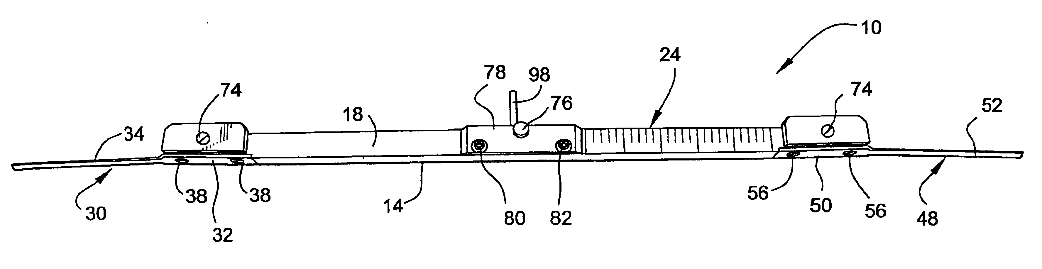
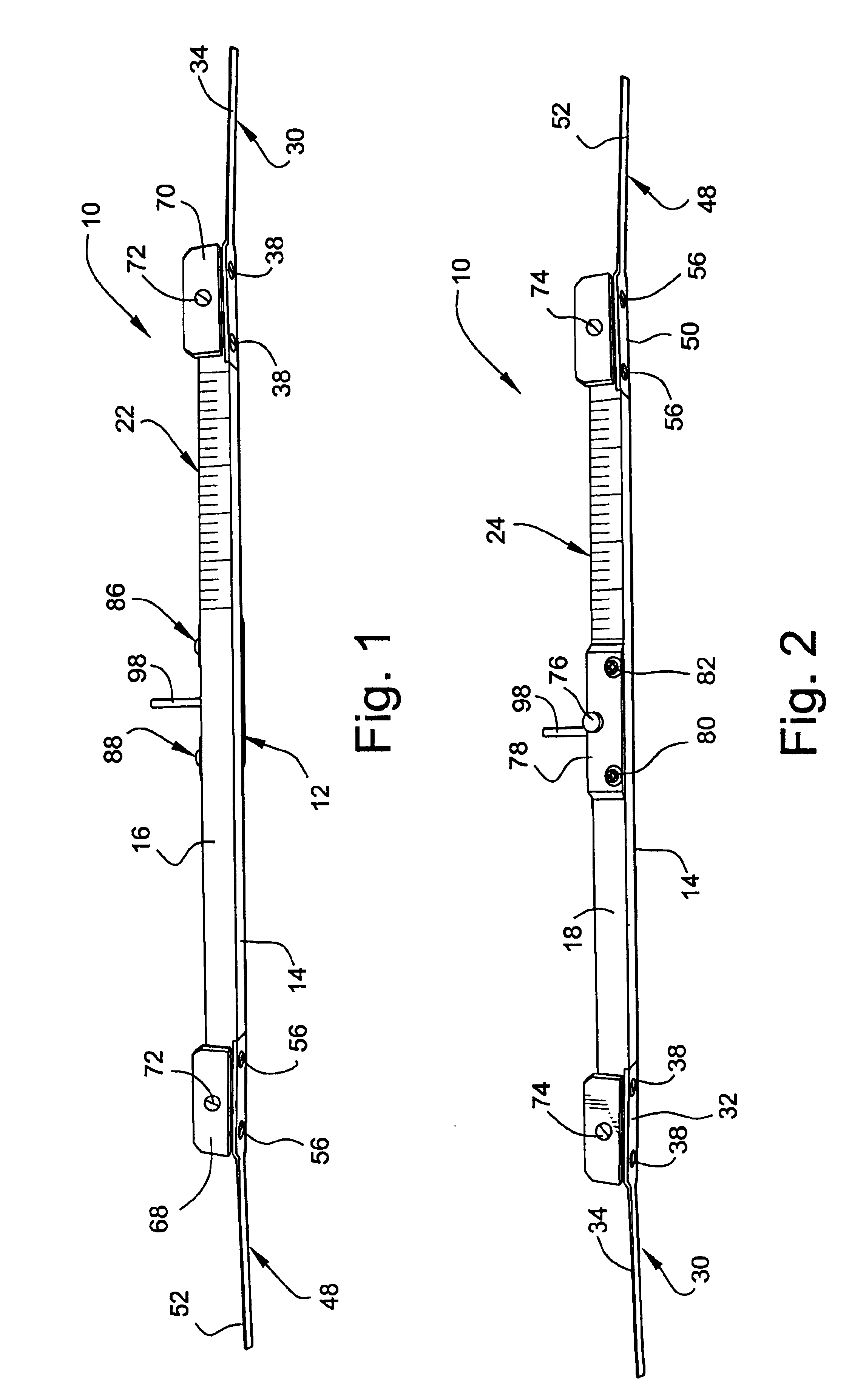
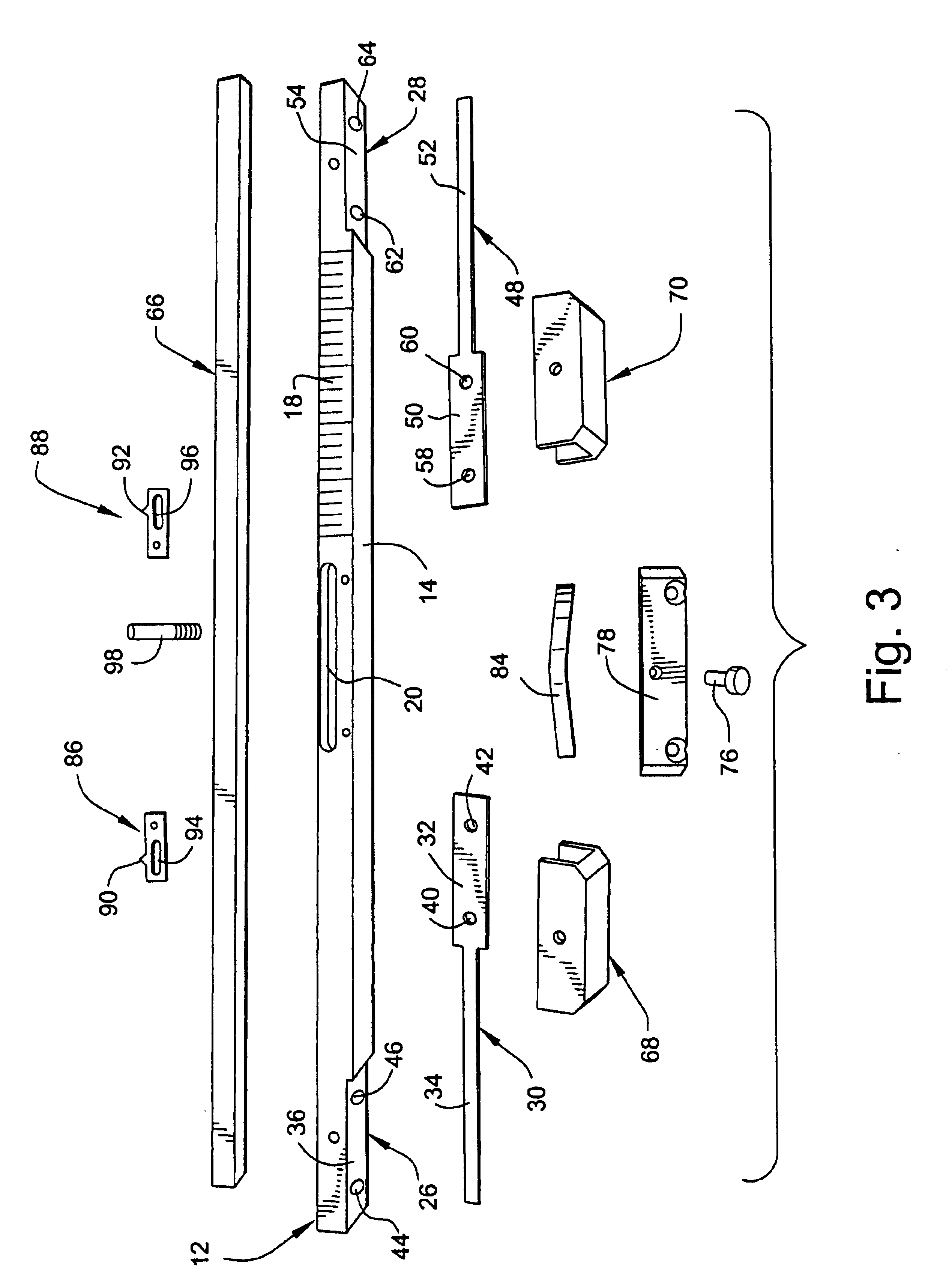
[0017]Referring to FIGS. 1-3, the clearance measurement gage 10 includes an elongated channel-shaped base 12 (or base channel) formed by a bottom wall 14 and a pair of perpendicular side walls 16, 18 that create a U-shaped cross-section. Side wall 18 is formed with an elongated, horizontally aligned slot 20, located centrally along the length dimension of the base 12. The function of slot 20 will be described in detail further below. Side wall 16 is provided with gradations for one scale 22 at one end of the gage corresponding to one range of rotor and packing clearances. Similarly, side wall 18 is provided at an opposite end of the gage with gradations for another scale 24 corresponding to a smaller range of rotor and packing clearances. This arrangement is for convenience and it will be understood that both scales could be located at opposite ends of one side of the base channel if desired, but this could cause some confusion reading the correct scale.

[0018]Note that the thickness...


PUM


Abstract

A measurement gage includes a base having two scales at opposite site ends of the base for different ranges of measurement. A tapered feeler gage elements projects axially from each of the opposite ends, and a slide bar is movable along the base, with an indicator fixed thereto for each of the two different scales. Movement of the slide bar in each of two opposite axial directions is calibrated to respective thicknesses of the tapered feeler gage elements.

Description

BACKGROUND OF INVENTION[0001]This invention relates to steam turbines used for power generation and, more specifically, to a gage used for measuring turbine rotor and packing clearances.[0002]The interpretation of the results of performance monitoring activities can be used to identify turbine internal problems that may cause a deterioration in performance, and to assist in planning maintenance required to address the problems. However, to restore performance during a turbine maintenance outage, the turbine components contributing to the performance loss need to be identified. This can best be done by conducting a turbine steam path evaluation.[0003]A steam path evaluation generally includes a detailed visual inspection of the steam path components and clearance measurements of the pickings and bucket tip spill strips. The visual inspection is used to evaluate and quantify the performance impact of degradation effects such as erosion, deposits, damage, preening, etc. Clearance measu...

Claims


Application Information

Patent Timeline
Patent Type & Authority Patents(United States)
IPC IPC(8): G01B5/14
CPCG01B5/14
Inventor KARWOWSKI, FRANCIS IGNATIUSCOREY, PETER R.
Owner GENERAL ELECTRIC CO
Why Eureka
Try Eureka