Single ball bearing lubricant and material evaluator

Inactive Publication Date: 2005-05-03
NAT AEROAUTICS & SPACE ADMINISTATION
View PDF17 Cites 6 Cited by
  • Summary
  • Abstract
  • Description
  • Claims
  • Application Information

AI Technical Summary

Benefits of technology

[0021]FIG. 3 is a schematic drawing of the data acquisition and control sys

Problems solved by technology

None of these apparatuses are believed to test the performance of lubricants or materials relating to a single ball bearing subjected to oscillating rotary motion.
The sensor integration described and shown in the '899 patent does not provide a testing apparatus for testing a monoball and the materials and/or lu

Method used


Image

  • Single ball bearing lubricant and material evaluator
  • Single ball bearing lubricant and material evaluator
  • Single ball bearing lubricant and material evaluator

Examples


Embodiment Construction

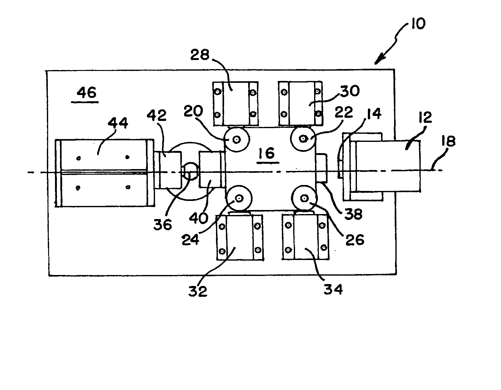
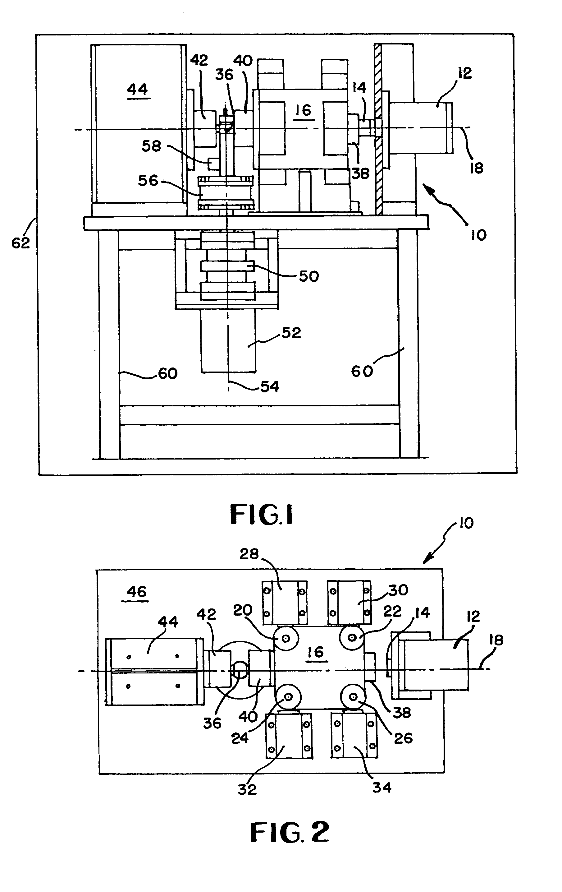
[0022]Accordingly, FIGS. 1 and 2 show a test apparatus 10 from a side and top view, respectively. The test apparatus 10 is comprised of a load applicator in the form of a hydraulic cylinder 12 which has an extendable piston 14 which contacts trolley 16. The hydraulic cylinder 12 of the load applicator is preferably configured to apply a load ranging from about 100 pounds to about 50,000 pounds of force or more. At the upper range of these loadings, the hydraulic cylinder 12 has been found to be a preferable load applicator. Other load applicators may be utilized in other embodiments.

[0023]The trolley 16 is preferably configured to travel along load axis 18. In fact, as shown in FIGS. 1 and 2, load axis 18 is linear and the trolley 16 is restricted to motion solely to travel along the load axis 18. Cam rollers 20,22,24,26 connected to trolley 16 are restrained from lateral motion by lateral supports 28,20,32,34. Accordingly, the trolley 16 is unable to travel in lateral motion by the...


PUM


Abstract

A test apparatus provides an applied load to a monoball through a trolley which moves along a loading axis. While applying the load to the monoball, the torque meter is in communication with the spherical monoball, and a load cell senses the application of applied force to the monoball. Meanwhile, a rotary actuary imports rotary oscillating motion to the monoball which is sensed by a position sensor and a torque meter. Accordingly, a processor can determine the coefficient of friction in substantially real time along with a cycles per second rate.

Description

ORIGIN OF THE INVENTION[0001]This invention was made by an employee of the United States Government together with government support under contract awarded by the National Aeronautics and Space Administration and may be manufactured and used by or for the Government for governmental purposes without the payment of any royalties thereon or thereof.BACKGROUND OF THE INVENTION[0002]1. Field of the Invention[0003]This invention relates to an apparatus for testing single ball bearings lubricants and / or materials in an oscillating rotary motion, and more particularly to such a test apparatus capable of providing environmental conditions including specific temperature, humidity, vacuum, atomic oxygen and other space simulated environmental conditions while monitoring the applied load, resisting torque, angle of rotation and / or coefficient of friction in real time.[0004]2. Prior Art[0005]A variety of lubricant and material test apparatuses have been produced. Falex Corporation maintains a w...

Claims


Application Information

Patent Timeline
IPC IPC(8): G01N33/26G01N33/30
CPCG01N33/30
Inventor HALL, PHILIP B.NOVAK, HOWARD L.
Owner NAT AEROAUTICS & SPACE ADMINISTATION
Why Eureka
Try Eureka