Removable cover piece for belt buckle

a belt buckle and cover piece technology, applied in the field of belt buckle cover pieces, can solve the problems of neck vertebrate discomfort or even injury, inconvenient use, inconvenient use, etc., and achieve the effects of enhancing convenience, facilitating gripping, and enhancing convenien

Inactive Publication Date: 2005-05-03
HUNG YUN TUNG
View PDF22 Cites 67 Cited by
  • Summary
  • Abstract
  • Description
  • Claims
  • Application Information

AI Technical Summary

Benefits of technology

This invention is about creating a new kind of belt buckle consisting of two separate parts - a buckle head and a cover piece. The buckle head has a special space designed for the cover piece which fits snugly over it. There's even a part called a nail grip that makes it easier to hold onto and remove the cover piece. The cover piece itself contains magnetic elements that match up with those on the buckle head to keep everything secure. Additionally, there are slots on the bottom of the buckle head that fit together like tracks to make sure the cover piece stays in place. Overall, this design provides more flexibility and ease of use than traditional belt buckles while still being cost-effective.

Problems solved by technology

The technical problem addressed by this patent is how to create a more convenient and comfortable belt buckle design that allows for easy removal and replacement of battery without having to detach the entire assembly from its original position on the belt.

Method used


Image

  • Removable cover piece for belt buckle
  • Removable cover piece for belt buckle
  • Removable cover piece for belt buckle

Examples


Embodiment Construction

[0019]To fully illustrate the function, structure and characteristic of the present invention the following preferred embodiments are selected in drawing forms to assist the explanation:

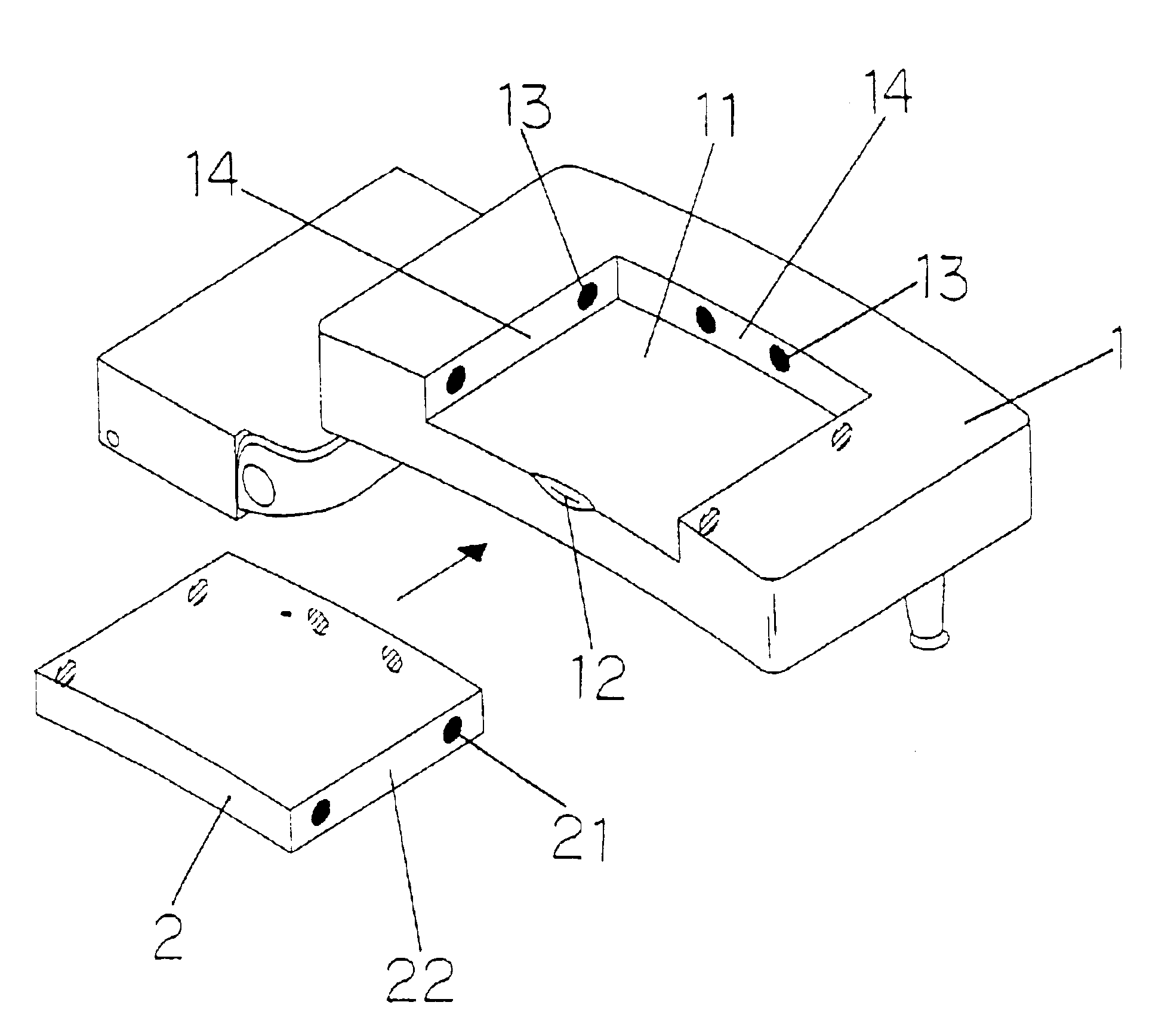
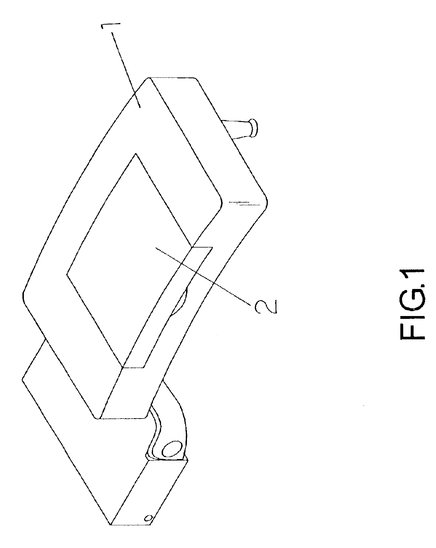
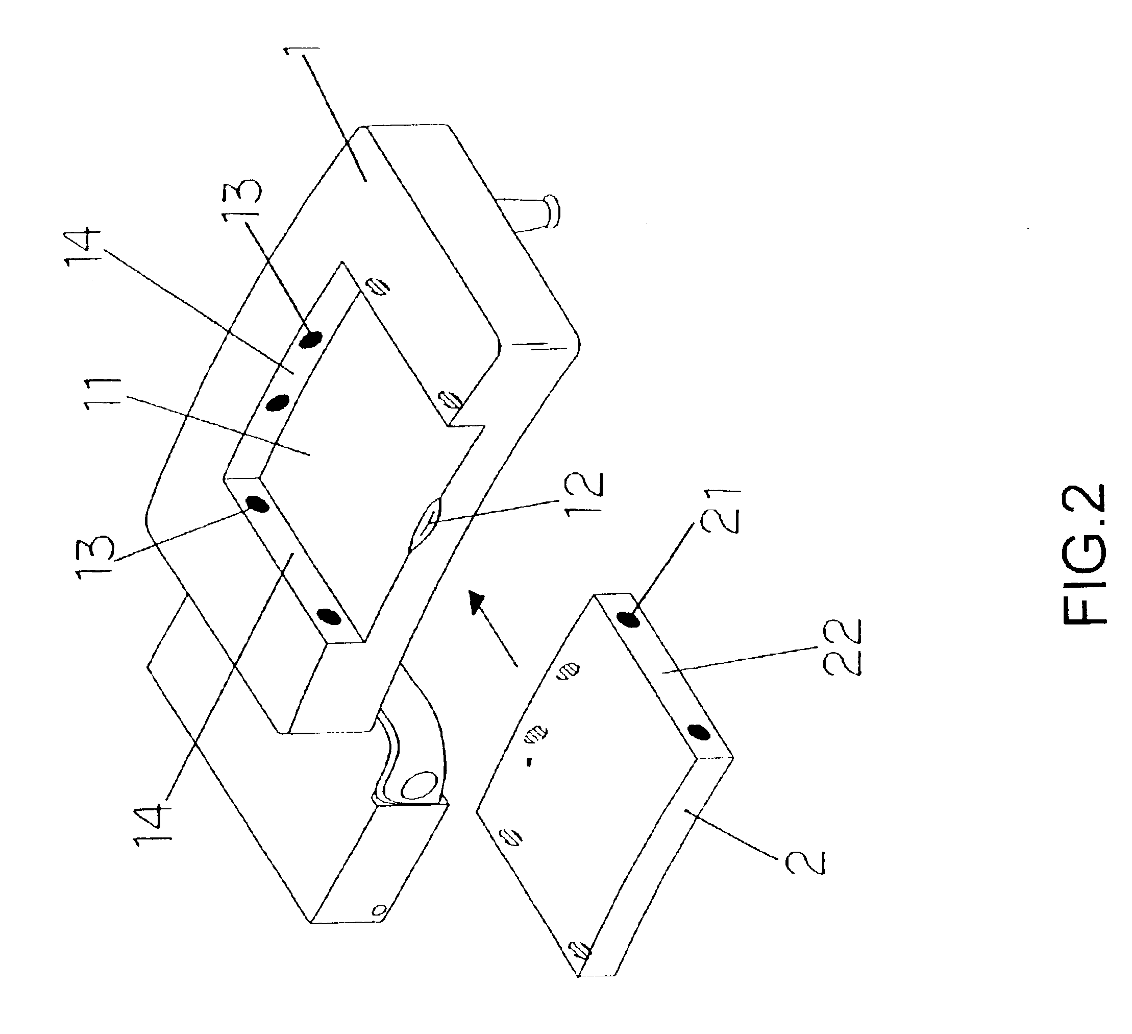
[0020]Referring to FIGS. 1 and 2, a perspective and exploded views showing the completed assembly and the separate components of the present invention, comprises of a separate buckle head (1) and a multi-function cover piece (2) where the buckle head (1) is fitted with a recessed trap (11), precisely dimensioned to receive the insertion of the cover piece (2) wherein the open end of the recessed trap (11 ) has a nail grip (12) for the easy gripping and removal of cover piece (2). The corresponding contact faces (22) (14) of cover piece (2) and recessed trap (11) are each installed with matching magnet elements (13) in order to secure cover piece (2) seated in the recessed trap (11).

[0021]As stated previously, the cover piece (2) can be applied to the embodiment of a radio, miniature flash light, time...


PUM


Abstract

The invention herein relates to a removable cover piece for belt buckle which is devised in two parts: a buckle head and a cover piece where the buckle head has a recessed trap precisely dimensioned to receive the cover piece. A nail grip is devised at the open end of the recessed trap so that the multi-functional cover piece inlayed in the trap can easily be gripped, removed or replaced with another cover piece. Upon the recessed trap contact faces are several magnet elements to meet the opposing magnet elements on the cover piece in order to secure the cover piece into the recessed trap. The present invention also features two slide guides at the base of recessed trap contact faces in response to the slide edges on the base of the cover pieces to form a track fitting assembly relationship, further securing the multi-functional cover pieces.

Description


Claims


Application Information

Patent Timeline
Owner HUNG YUN TUNG
Why Eureka
Try Eureka