Hollow cathode target and methods of making same

a hollow cathode and target technology, applied in the field of hollow cathode targets, can solve the problems of affecting the performance of the sputtering system, affecting the life of the target, and bringing about the good deposition uniformity that it provides, so as to achieve the effect of reliable, simple and cost-effective magnetron sputtering system

Inactive Publication Date: 2005-05-03
GLOBAL ADVANCED METALS USA
View PDF23 Cites 54 Cited by
  • Summary
  • Abstract
  • Description
  • Claims
  • Application Information

AI Technical Summary

Benefits of technology

[0011]The present invention is also directed to a method of making a hollow cathode magnetron sputtering target that is suitable for causing a uniform film of sputtered material to be deposited onto a substrate, and to a sputtering target made according to the method. The present invention may be used in different

Problems solved by technology

A disadvantage of the above technique, however, is that the good deposition uniformity that it provides is brought about at the expense of very non-uniform erosion of the target.
Thus, target life suffers.
These techniques tend to impart metallurgical inhomogeneities to the cathode, which detrimentally impact sputtering performance.
Such metallurgical inhomogeneities may create stray magnetic fields that impede the sputtering process.
Likewise, deep drawing or spinning of annealed or stress-relieved plate may generate minor amounts of strain

Method used


Image

  • Hollow cathode target and methods of making same
  • Hollow cathode target and methods of making same
  • Hollow cathode target and methods of making same

Examples


examples

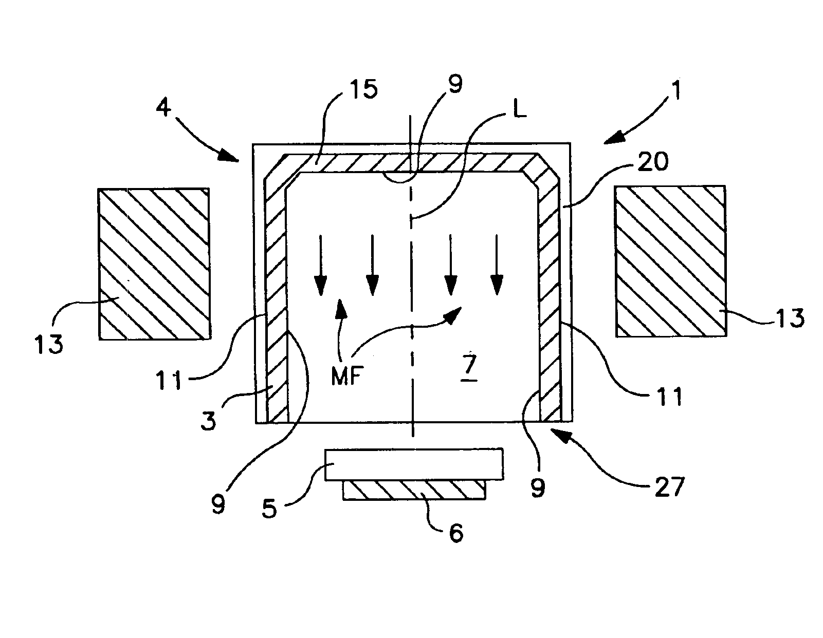
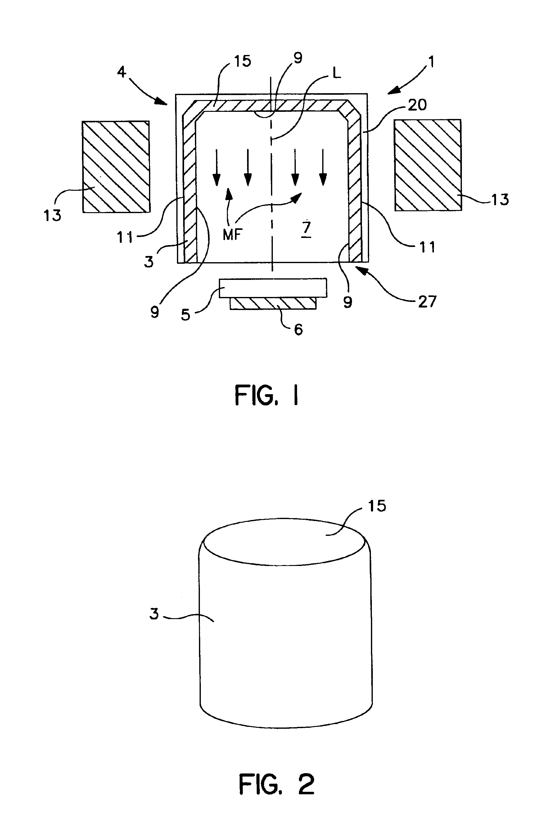
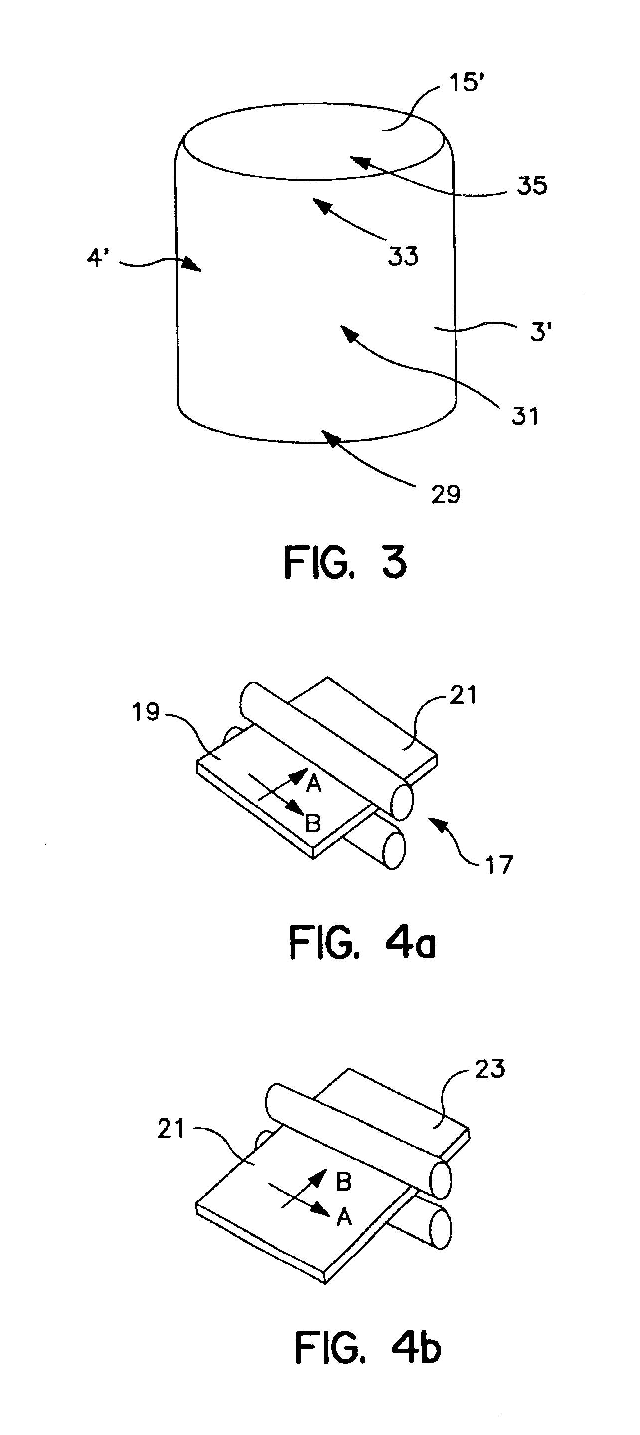
[0048]Two commercially available niobium plates and two commercially available tantalum plates from Cabot Corporation were used in the examples. Each of the niobium and tantalum plates were cross rolled several times as described in the present application. The plates originally had a thickness of 3.5 inches and through the cross-rolling process resulted in a thickness of 0.500 inches. The cross cold rolling was accomplished such that the rolling was done the same number of times in one direction and in a second direction perpendicular to the first direction. A disc having a dimension of 0.500″×18.0″ diameter was cut from each of the plates. In making the preform, each of the discs were drawn into a preform which had the shape of a cup by the use of a 1000 ton press. The cup shaped preform had the following dimensions after being subjected to the 1000 ton press: about 6.6″ height with about 0.500″ wall thickness, wherein the wall had a 1° tapered edge. The inner diameter of the cup ...


PUM

PropertyMeasurementUnit
Fractionaaaaaaaaaa
Grain sizeaaaaaaaaaa

Abstract

Sputtering targets and methods of making sputtering targets are described. The method includes the steps of: providing a sputtering metal workpiece made of a valve metal; transverse cold-rolling the sputtering metal workpiece to obtain a rolled workpiece; and cold-working the rolled workpiece to obtain a shaped workpiece. The sputtering targets exhibits a substantially consistent grain structure and/or texture on at least the sidewalls.

Description

[0001]This application claims the benefit under 35 U.S.C. §119(e) of prior U.S. Provisional Patent Application Nos. 60 / 253,116 filed Nov. 27, 2000, and 60 / 295,417 filed Jun. 1, 2001, which are incorporated in their entirety by reference herein.BACKGROUND OF THE INVENTION[0002]The present invention relates to a sputtering target and to methods of making the same.[0003]Various sputtering techniques are used in order to affect the deposition of the film over the surface of the substrate. Deposited metal films, such as metal films on a thin film semiconductor device, can be formed by a magnetron sputtering apparatus or other sputtering techniques. The magnetron sputtering apparatus induces plasma ions of a gas to bombard a target causing surface particles of the target material to be ejected therefrom, and to be deposited as a film or layer on the surface of a substrate. Conventionally, a sputtering source in the form of a planar disc or rectangle is used as the target, and ejected atom...

Claims


Application Information

Patent Timeline
IPC IPC(8): C23C14/34C22B5/12B21B3/00C22F1/00C22F1/08C22F1/18
CPCC23C14/3407H01J37/3491H01J37/342C23C14/3414C23C14/34
Inventor FORD, ROBERT B.MICHALUK, CHRISTOPHER A.
Owner GLOBAL ADVANCED METALS USA
Why Eureka
Try Eureka