Microstrip antenna for an identification appliance

a microstrip antenna and appliance technology, applied in the direction of mechanical actuation of burglar alarms, near-field systems using receivers, instruments, etc., can solve the problems of poor transmission, inefficient radiators and receptors of antennas which are a small fraction of wavelengths in linear dimensions, and inconvenient operation

Inactive Publication Date: 2005-05-03
PRECISION DYNAMICS CORPORATION
View PDF7 Cites 266 Cited by
  • Summary
  • Abstract
  • Description
  • Claims
  • Application Information

AI Technical Summary

Benefits of technology

[0012]Other systems, methods, features and advantages of the invention will be or will become apparent to one with skill in the art upon examination of the following figures and detailed description. It is intended that all such additional systems, methods, features and advantages be included within this description, be within the scope of the invention, and be protected by the accompanying claims.

Problems solved by technology

However, when an identification band transmits information to another device or receives information from another device, the accuracy of the information may be compromised by poor transmission.
However, a typical wristband is six inches in length, which must include an antenna, while the wavelength at 13.5 MHz is 73 feet, and it is well known that antennas which are a small fraction of a wavelength in linear dimensions are very inefficient radiators and receptors.
As a result, the useful range of operation may be very limited and sometimes can be just a few inches from the reader antenna.
This is a significant disadvantage which may limit the usefulness of HF tags in identification bands and may render them unusable, for example, in personnel location or ingress / egress alarm applications.
However, compared to the HF band, the radiation and reception of EM waves at these higher frequencies bands are affected much more strongly by obstacles and materials in the immediate environment of the antenna as a result of the shorter wavelengths.
In particular, a loop or dipole antenna, operating on or adjacent to the human body, for example in a band, will be severely detuned and possibly rendered inoperable, with a commensurate degradation of the communication link.
Thus the usability of these antennas in identification-bands with RFID capability is very limited.
The aforementioned antenna detuning and communication degradation problems are directly attributable to the fact that an isolated (free of nearby obstacles) loop or dipole antenna normally radiates EM energy in opposite directions.
But, when on or near the surface of a human body, the reactive near fields (the electric and magnetic fields closest to the antenna) are distorted by the human tissue, causing an impedance mismatch between the antenna and the circuit to which it is immediately connected.
This mismatch effectively detunes the antenna and reduces the amount of EM energy radiated in the direction away from the human body.

Method used


Image

  • Microstrip antenna for an identification appliance
  • Microstrip antenna for an identification appliance
  • Microstrip antenna for an identification appliance

Examples


Embodiment Construction

[0022]As used in this specification, the meaning of “in,” whether alone or in a compound such as “therein,” includes “in” and “on”; “radio frequency identification” and “RFID” refer to identification by radio frequency communication.

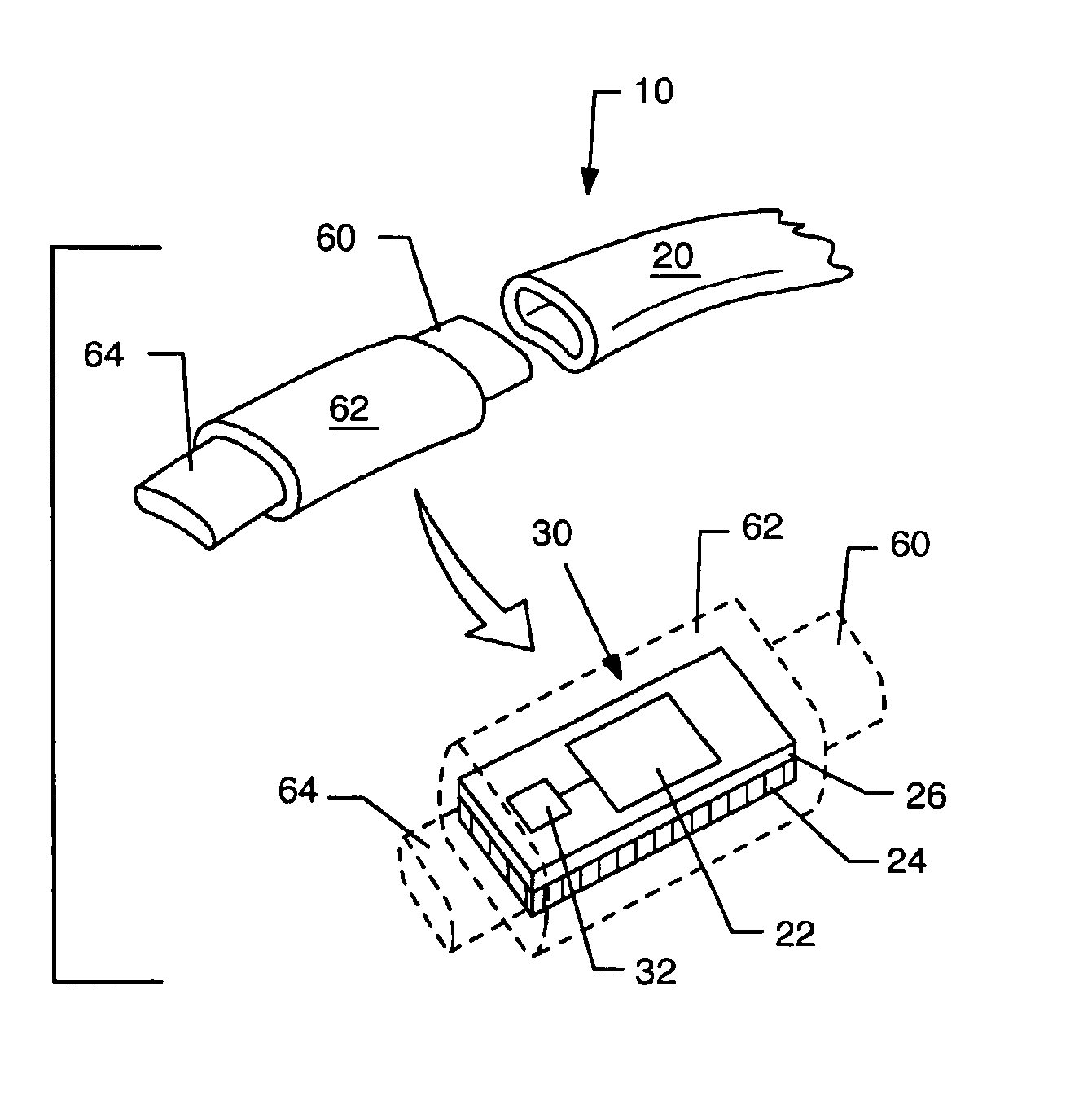
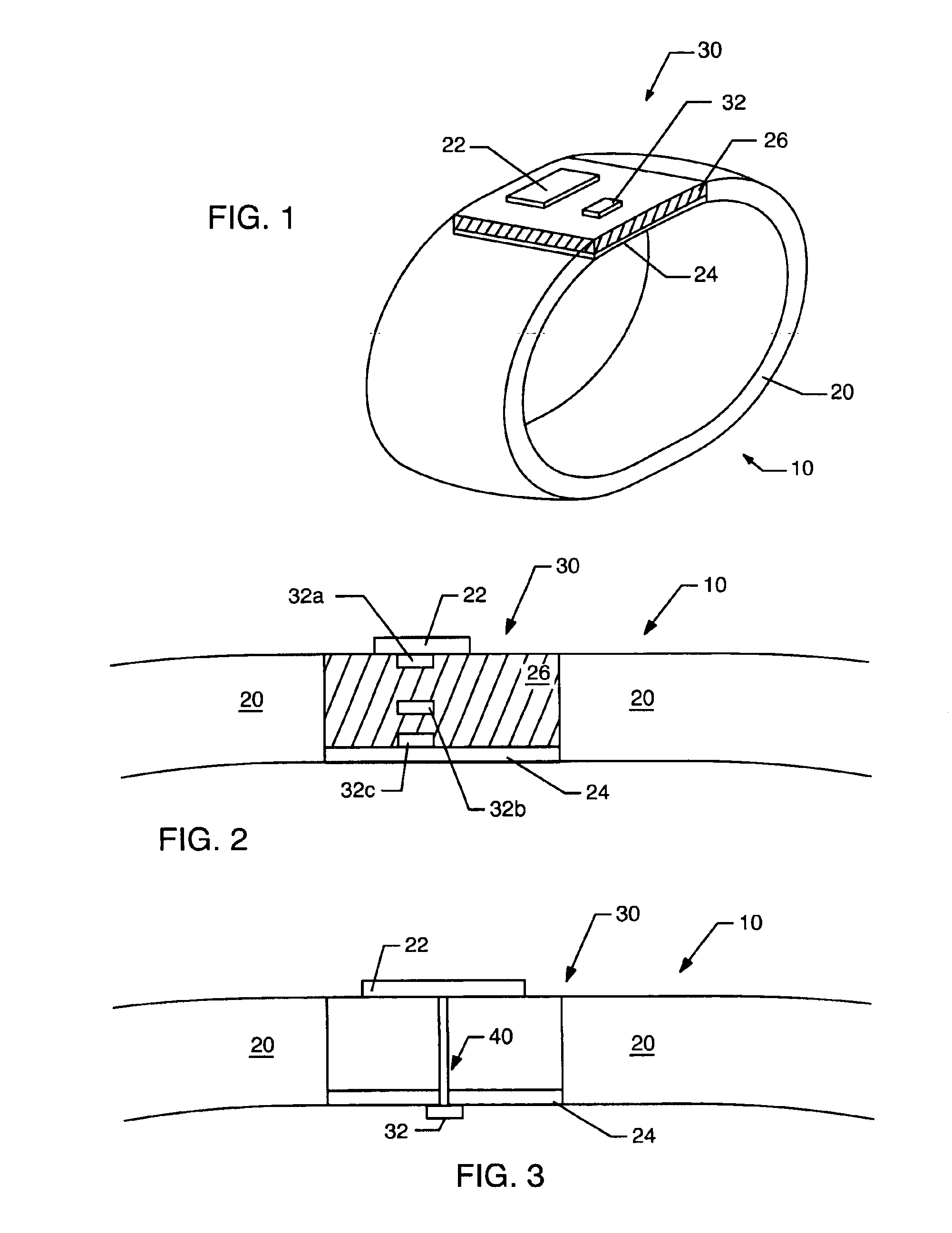
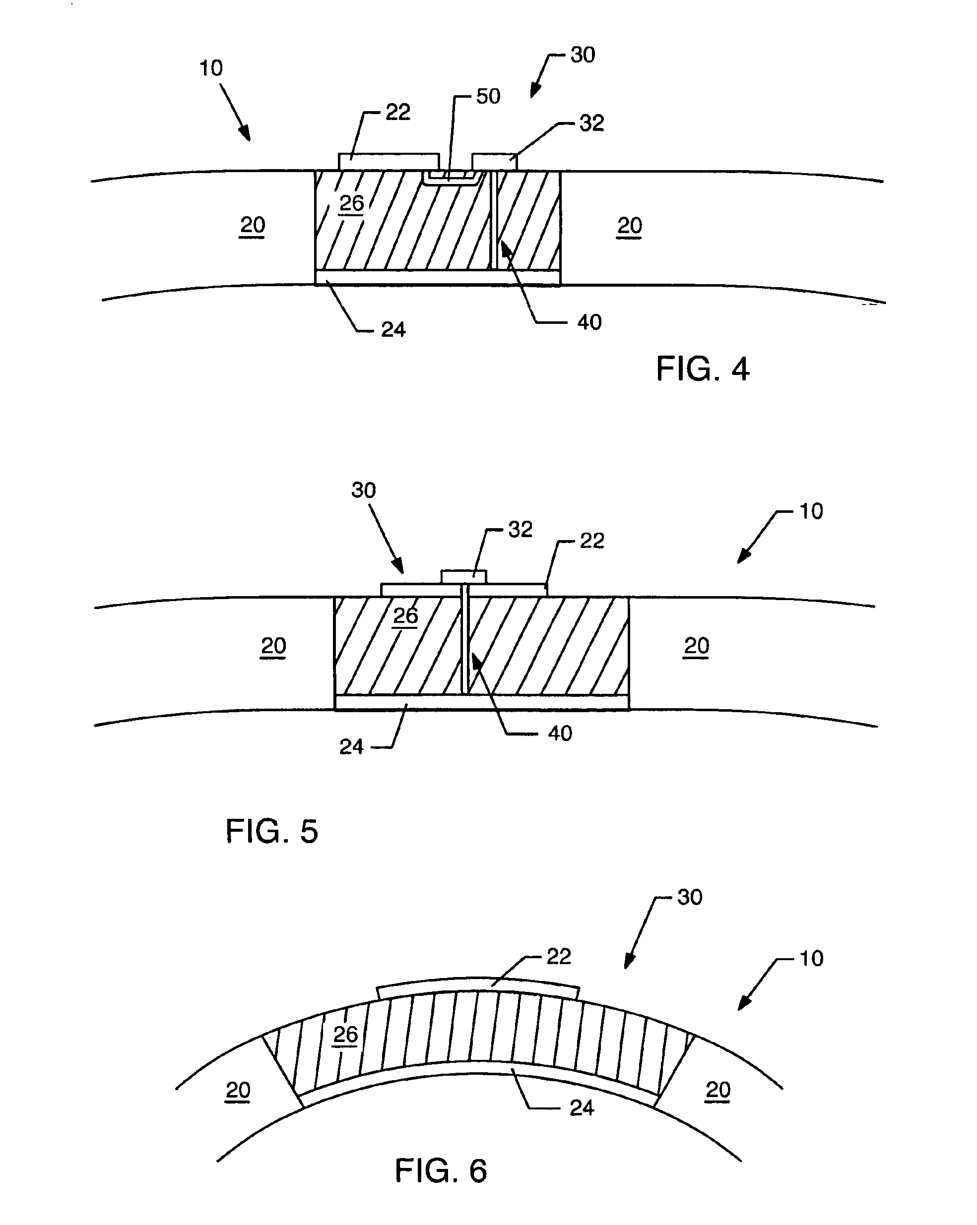
[0023]FIG. 1 is a representation of an example embodiment of an identification appliance 10 containing a microstrip antenna 30 as a part thereof. The microstrip antenna 30 is preferably a patch antenna. The identification appliance 10 has a structure 20 carrying a communication circuit 32, such as a RFID circuit. The communication circuit 32 may be adapted to communicate with any type of system, network, or device and may use any communication protocol, including Bluetooth or IEEE 802.11. In this embodiment as a band, the identification appliance 10 includes a structure 20 that is suitable to be worn by, attached to, or carried by a person. Preferably, the identification appliance 10 is a wristband and the structure 20 is an elongate, flexible wristband ...


PUM


Abstract

An identification appliance, such as a wristband, bracelet, patch, headband, necklace, card, sticker, or other wearable appliance, has an improved patch or microstrip antenna. The microstrip antenna comprises a conductive patch layer, a conductive ground layer and a dielectric layer in between the conductive layers. The microstrip antenna is mounted to or disposed in the identification appliance, where preferably the ground layer is closest to the user and the patch layer is furthest from the user. Electronic circuits may be located in the dielectric layer, on a surface of a conductive layer, or on another part of the identification appliance. Connecting holes through the dielectric layer may allow circuits to be connected to a conductive layer or layers. This improved antenna resolves detuning and communication degradation problems.

Description

FIELD OF THE INVENTION[0001]The field of the invention relates generally to antennas for identification appliances such as wristbands, and in particular to a microstrip antenna or patch antenna for identification appliances such as wristbands.BACKGROUND OF THE INVENTION[0002]This disclosure contemplates an improved identification wristband, bracelet, patch, headband, necklace, card, sticker, or other wearable appliance, which for the sake of convenience, are collectively referred to as a “band” or as an “identification appliance”. Identification bands have become a convenient and effective way of identifying people without permanently marking them. A principle advantage of a band is that it is ultimately removable. Identification bands typically consist of a flexible wrist strap having a length greater than its width, and a closure or securement device for attaching and maintaining the band securely around the wearer's wrist. A portion of the band may be used for imprinting or other...

Claims


Application Information

Patent Timeline
Patent Type & Authority Patents(United States)
IPC IPC(8): H01Q1/22H01Q1/27H01Q9/04H01Q1/38G06K19/077G06K19/07H01Q1/44H04B5/02
CPCG06K19/07762H01Q1/22H01Q1/2225H01Q9/0471H01Q1/38H01Q9/0407H01Q1/273
Inventor BEIGEL, MICHAEL L.TUTTLE, JOHN R.BELL, H. CLARK
Owner PRECISION DYNAMICS CORPORATION
Why Eureka
Try Eureka