High dynamic range image editing

a high-dynamic range, image editing technology, applied in image enhancement, electronic editing, digitised analogue information signals, etc., can solve the problems of affecting the conversion process, and affecting the quality of images, etc., to achieve the effect of not reducing the range of light intensity levels

Inactive Publication Date: 2005-05-03
CALIFORNIA UNIV OF SOUTHERN
View PDF10 Cites 61 Cited by
  • Summary
  • Abstract
  • Description
  • Claims
  • Application Information

AI Technical Summary

Benefits of technology

[0014]Another object of the invention is to facilitate the editing of a high dynamic range image with a low dynamic range image editing system without significant loss of dynamic range information.
[0016]A still further object of the invention is to reduce delays in image editing systems caused by calculations of a non-linear tone mapping curve or function, such as a gamma correction curve.
[0019]The scaled version of the image file is preferably displayed. One or more image editing tools preferably edit the appearance of the image that is displayed on the display. These tools also edit the pixels in the image file in a manner that is consistent with the edits that are displayed, without reducing the range of light intensity levels in the image file.

Problems solved by technology

Unfortunately, most digital editing systems have a low dynamic range, meaning that the contrast ratio between the lightest and darkest pixel that they can display is small.
Important variations at very low intensities and at very high intensities are usually lost in the conversion process.
A still further problem with existing low dynamic range image editing systems is that the differences in assigned pixel intensity values often fail to bare a linear relationship to the differences in the intensity levels of the portions of the actual scene that these pixels represent.
These non-linearities cause further distortions, in addition to the loss of information that occurs when a high dynamic range image is converted to the low dynamic range needed for the image editing system.
A still further problem with image editing systems is that the editing process is often slowed by repeated applications of a non-linear tone mapping curve or function, such as a gamma correction curve.
Unfortunately, this typically involves complex computations that take significant time to compute during the editing process.

Method used


Image

  • High dynamic range image editing
  • High dynamic range image editing
  • High dynamic range image editing

Examples


Embodiment Construction

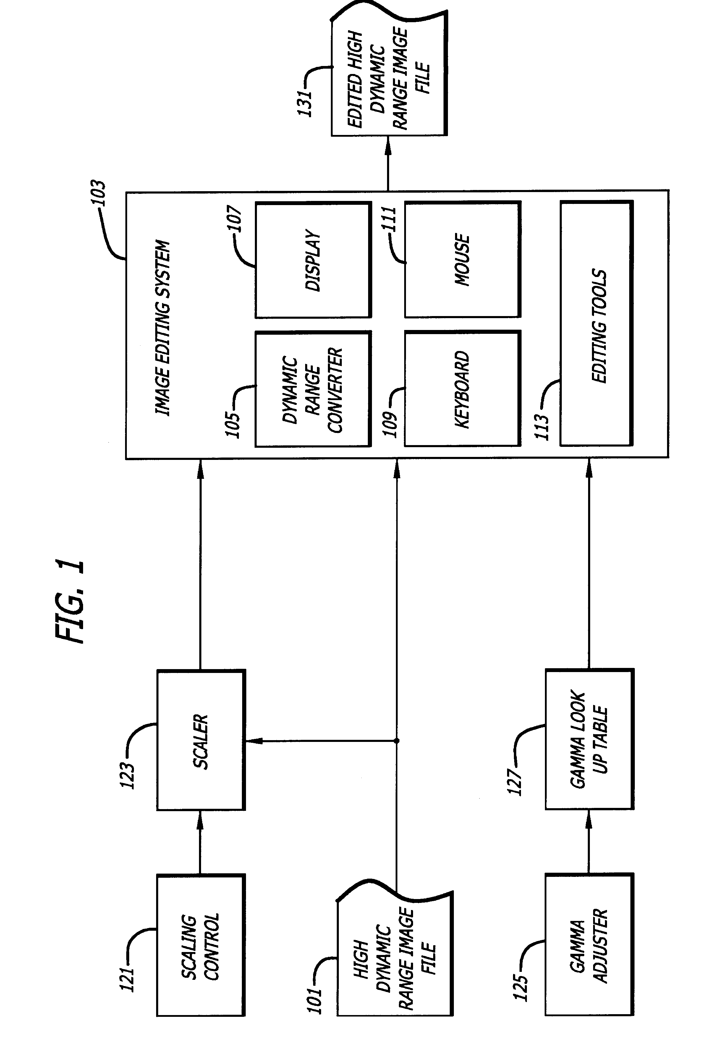
[0033]FIG. 1 illustrates certain components of one embodiment of the invention.

[0034]As shown in FIG. 1, a high dynamic range image file 101 is processed by an image editing system 103. The image editing system 103 includes a dynamic range converter 105, a display 107, a keyboard 109, a mouse 111 and image editing tools 113.

[0035]A user-operable scaling control 121 is in communication with a scaler 123 which, in turn, is in communication with the image file 101 and the image editing system 103. A gamma adjuster 125 is in communication with a gamma lookup table 127 that is in communication with the image editing system 103.

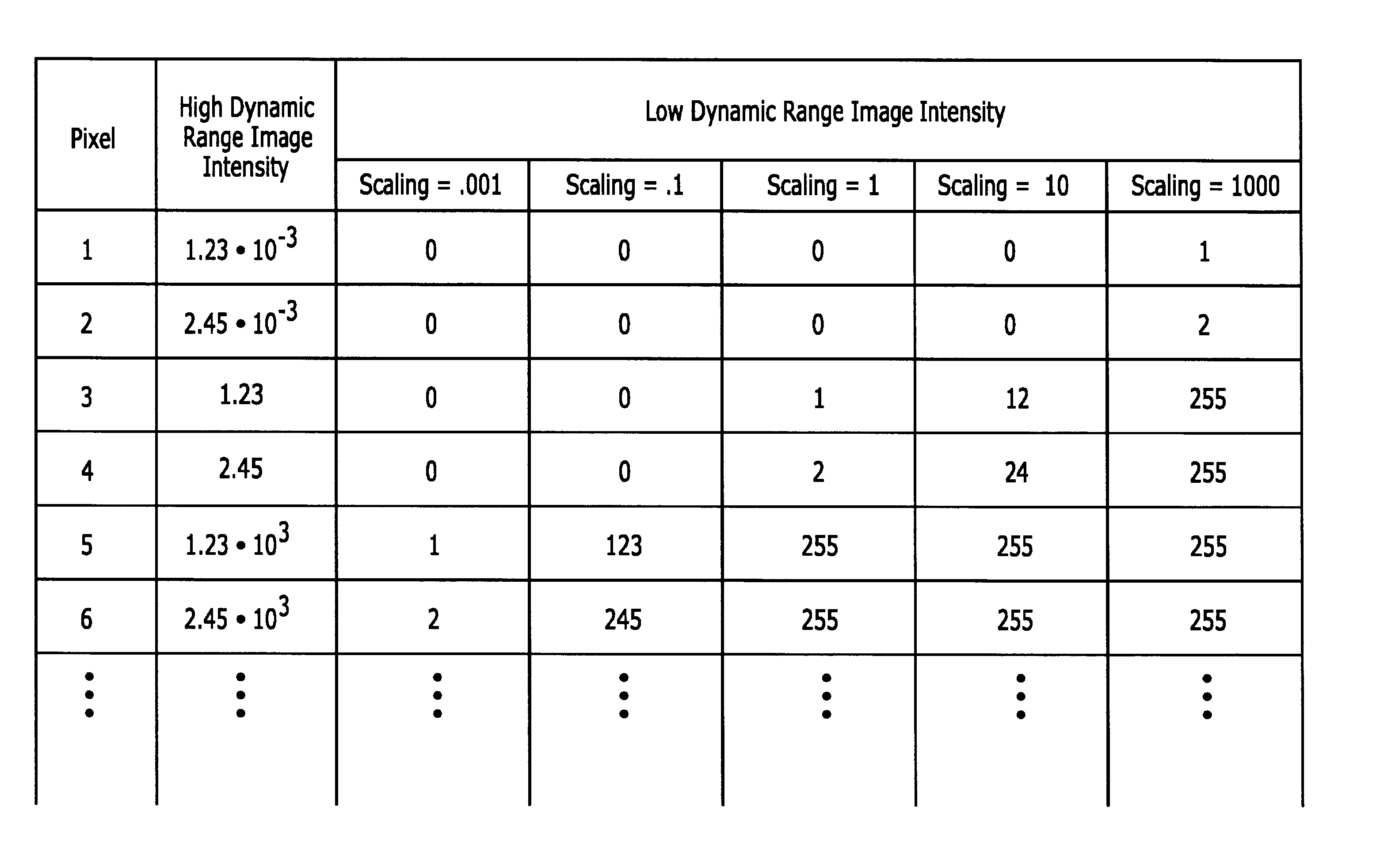
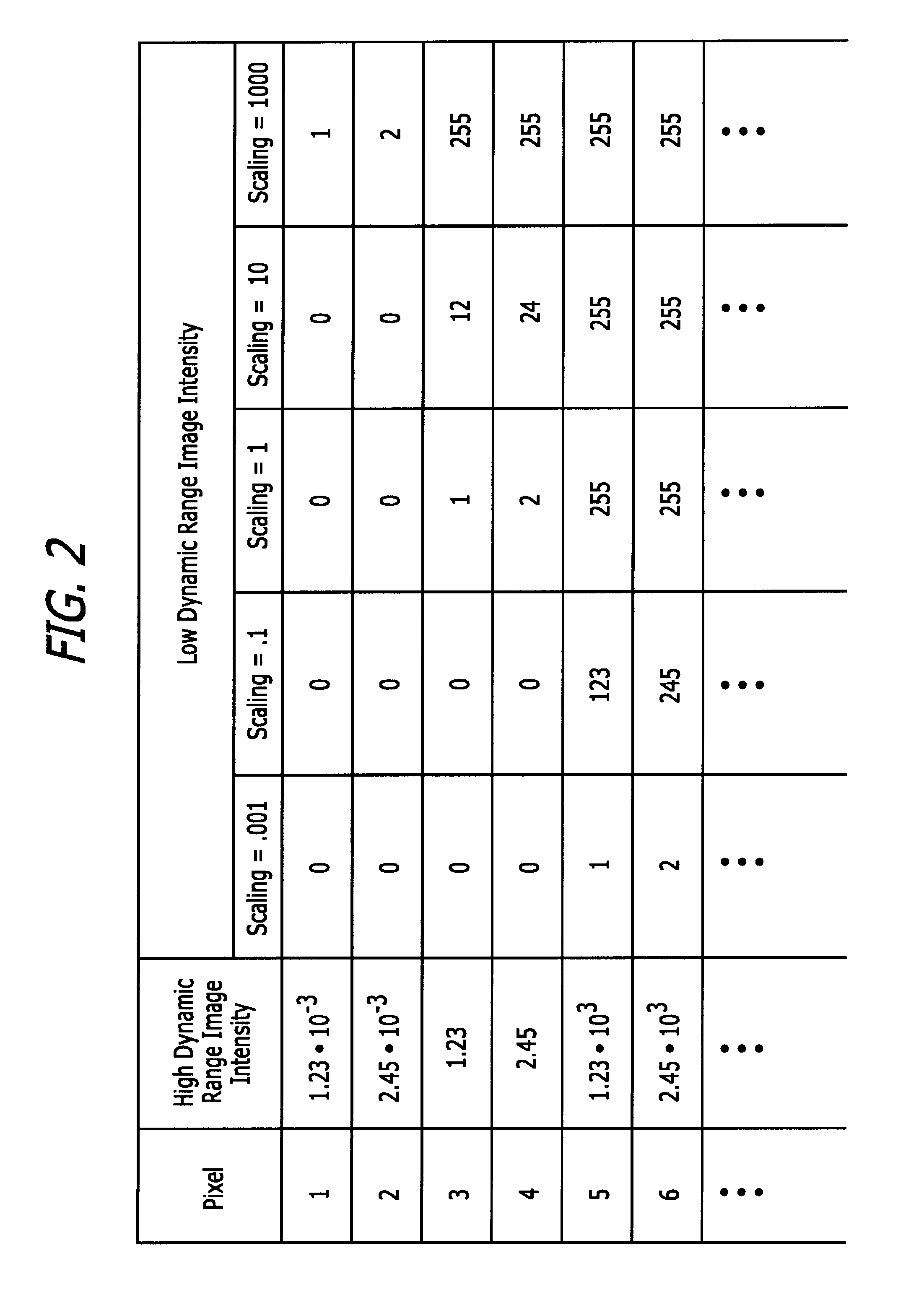
[0036]The image editing system 103 is intended to represent any of the image editing systems that are now known or hereinafter created. At least some aspect of the image editing system 103 will typically be limited to a dynamic range that is less than the dynamic range of the image file 101.

[0037]The “dynamic range” of an image is the contrast ratio between its bri...


PUM

PropertyMeasurementUnit
light intensityaaaaaaaaaa
areaaaaaaaaaaa
coloraaaaaaaaaa

Abstract

A high dynamic range image editing system for editing an image file having pixels spanning a first range of light intensity levels in an image editing system that only displays differences in the light intensity levels of pixels within a second range of light intensity levels that is less than the first range of light intensity levels, without reducing the range of light intensity levels in the image file.

Description

CROSS REFERENCES TO RELATED APPLICATIONS[0001]This application is related to and claims the benefit of the filing date of the following U.S. provisional applications: HDR Shop, Application No. 60 / 297,096, filed Jun. 8, 2001; and High Dynamic Range Image Processing System and Method, Application No. 60 / 297,397, filed Jun. 11, 2001. The contents of both of these provisional applications are incorporated herein by reference.BACKGROUND OF THE INVENTION[0002]1. Field of the Invention[0003]This invention relates to image editing systems and methods. More particularly, this invention relates to image editing systems and methods that work with images stored in digital format.[0004]2. Description of Related Art[0005]The “dynamic range” of a scene is the contrast ratio between its brightest and darkest parts. A plate of evenly lit mashed potatoes outside on a cloudy day has a very low dynamic range. The interior of an ornate cathedral with light streaming in through its stained-glass windows ...

Claims


Application Information

Patent Timeline
Patent Type & Authority Patents(United States)
IPC IPC(8): G06T11/00G11B27/034G11B27/031
CPCG06T11/001G11B27/034G09G5/02G09G5/06G06T5/009G06T5/007G06T2207/20208
Inventor DEBEVEC, PAUL E.HAWKINS, TIMOTHY S.TCHOU, CHRIS D. X. N.
Owner CALIFORNIA UNIV OF SOUTHERN
Why Eureka
Try Eureka