Stationary fluid replacement system and methods of use

a fluid replacement system and stationary technology, applied in liquid handling, machines/engines, packaging goods types, etc., can solve the problems of dual or plural service bays of the stationary system, underground storage and above ground gravity assisted feeds

Inactive Publication Date: 2005-05-10
AWAD ADAM
View PDF11 Cites 11 Cited by
  • Summary
  • Abstract
  • Description
  • Claims
  • Application Information

AI Technical Summary

Benefits of technology

[0017]Another objective is to provide such an invention capable of moving fluids between containers and an automotive fluid system for cleaning and refilling with only an initial vacuum drawn on one or more containers.

Problems solved by technology

The prior art teaches the use of fluid exchange systems for providing automotive maintenance and especially in the field of radiator cleaning and refilling, but does not teach a stationary system dual or plural service bays and with underground storage and above ground gravity assisted feeds.

Method used


Image

  • Stationary fluid replacement system and methods of use
  • Stationary fluid replacement system and methods of use
  • Stationary fluid replacement system and methods of use

Examples


Embodiment Construction

[0025]The above described drawing figures illustrate the invention in at least one of its preferred embodiments, which is further defined in detail in the following description.

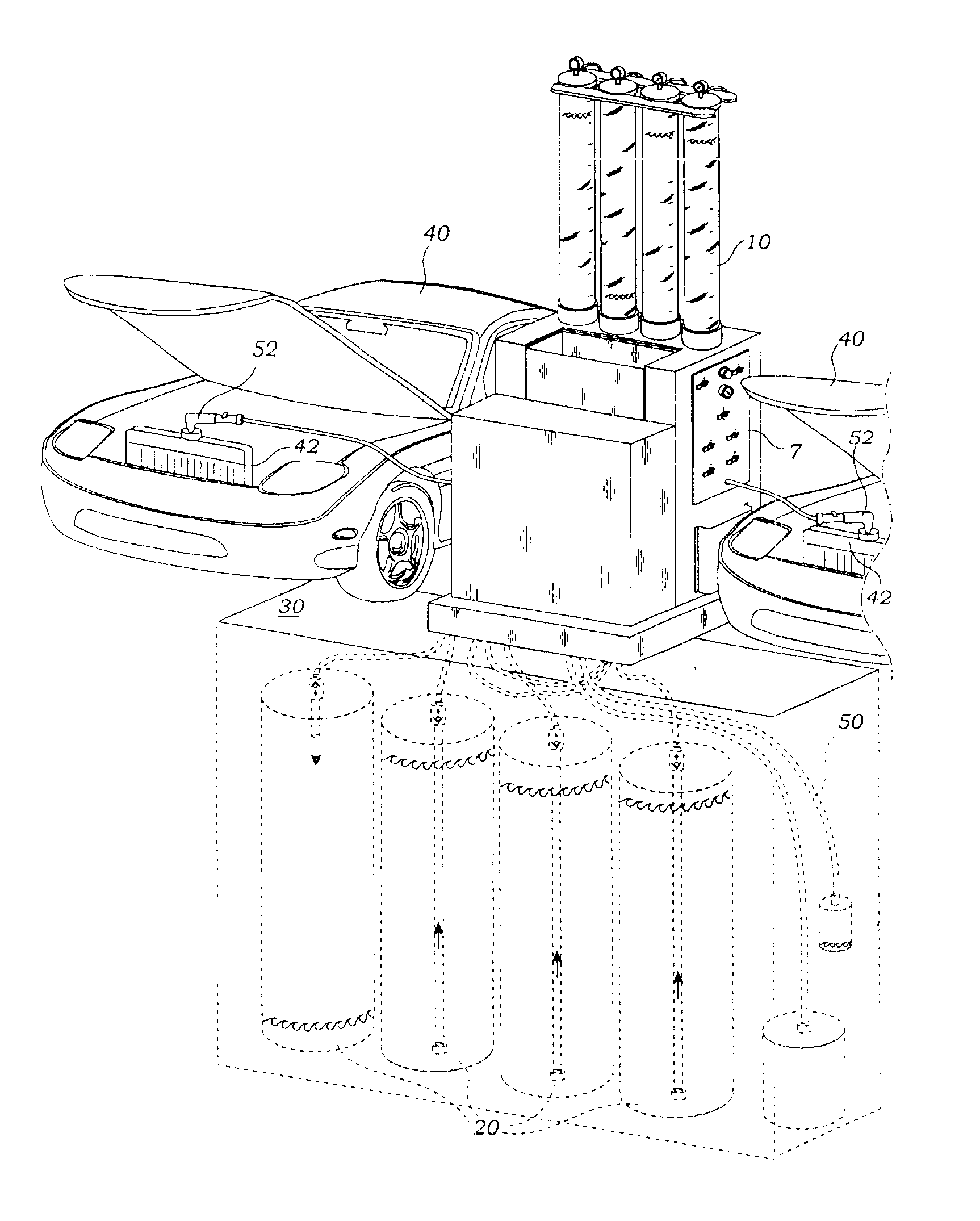
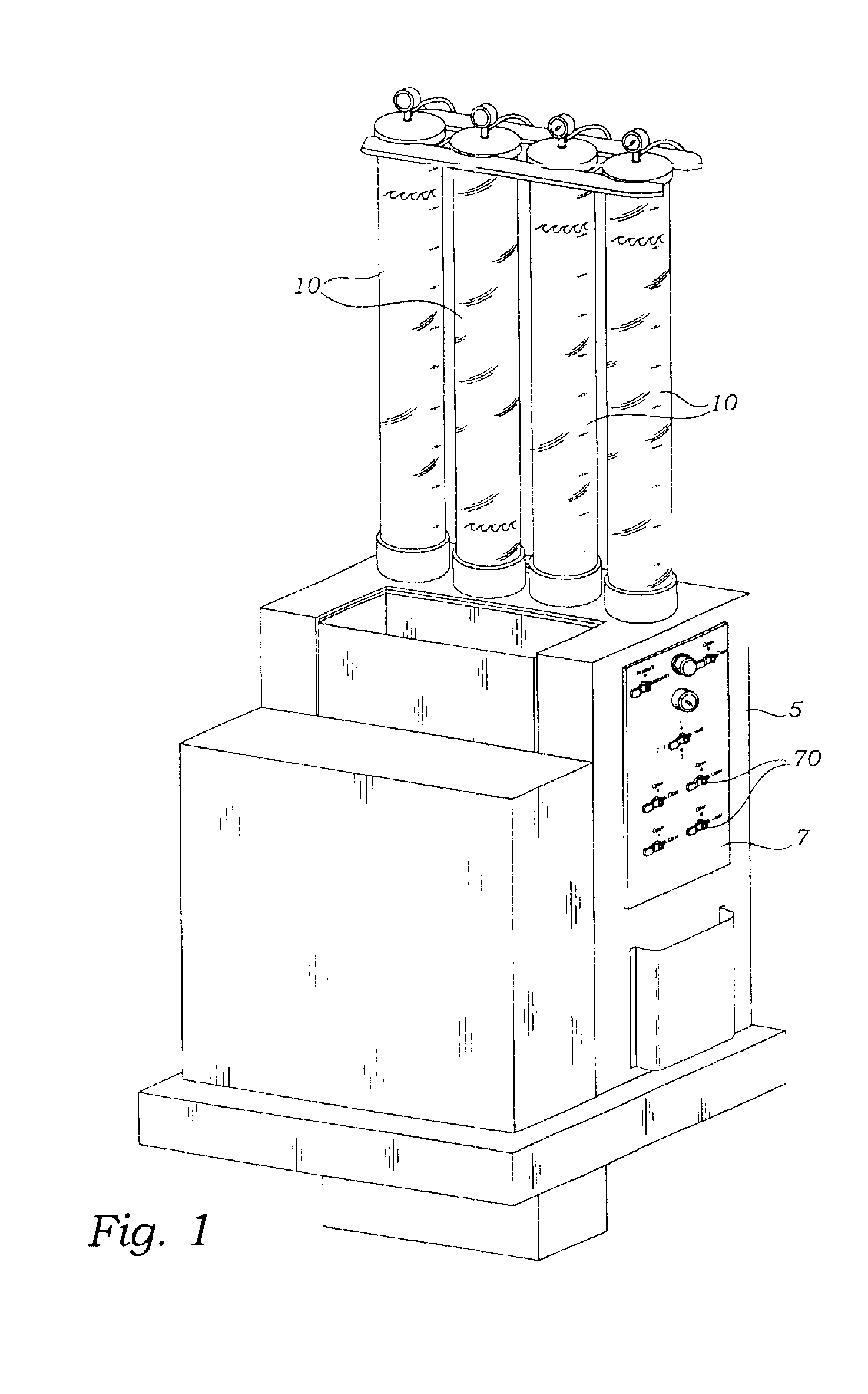
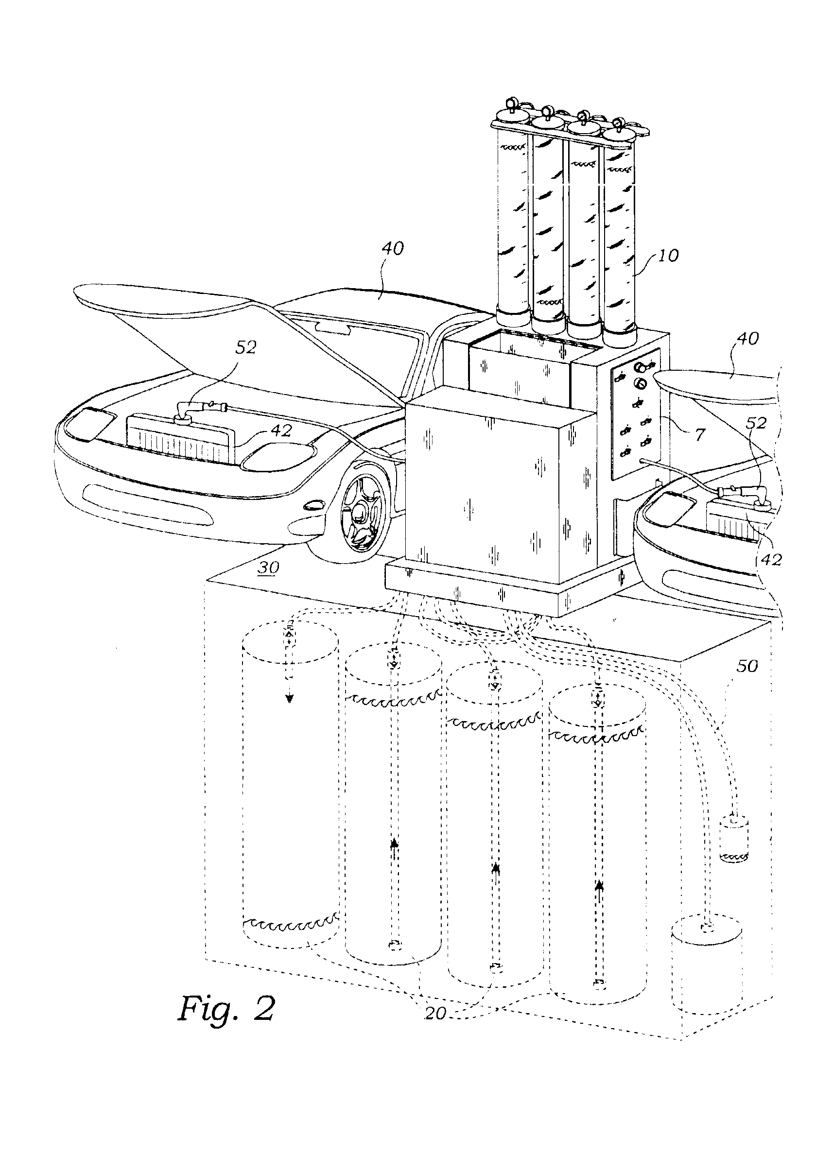
[0026]The present invention is a fluid exchange system including an apparatus and method of use. The apparatus includes a stationary control station 5 as best shown in FIG. 1. Plural first fluid containers 10 are mounted above, and preferably on top, of the control station 5 as would be easily accomplished by those of skill in the art. These first fluid containers 10 are preferably transparent or translucent so that one may monitor the fluid levels. Plural second fluid containers 20 are mounted below the control station 5, preferably below a driveway 30 enabling automotive vehicles 40 access to the control station 5. Preferably the control station 5 is mounted on, and is fixed to, the driveway 30 or its appurtenances so that it (the control station 5) is not movable. A conduit means 50 such as a network of tu...


PUM

PropertyMeasurementUnit
driving forcesaaaaaaaaaa
gravityaaaaaaaaaa
suctionaaaaaaaaaa

Abstract

A fluid exchange apparatus provides a stationary control station with plural first and second fluid containers mounted on top and below the control station. Conduits interconnect the fluid containers with the control station for fluid transfer and fluid interchange with an automotive vehicle or other equipment. Suction and pressure are provided for driving fluids through a fluid switching system. The control station provides dual control panels enabled for servicing two equipments simultaneously.

Description

RELATED APPLICATIONS[0001]This is a continuation-in-part application of a prior filed and currently application having Ser. No. 10 / 254,141 filed Sep. 24, 2002 now U.S. Pat. No. 6,604,557. Other applications related to the present application, and pending on the filing date of the present application are: Ser. No. 10 / 266,529 filed Oct. 8, 2002, Ser. No. 10 / 287,574 filed Nov. 4, 2002, Ser. No. 10 / 634,271 filed Aug. 4, 2003 and Ser. No. 10 / 634,976 filed on Aug. 4, 2003. The status of these other applications on Oct. 28, 2004 is: '529-pending; '574-issued as U.S. Pat. No. 6,688,340 on Feb. 10, 2004; '271-issued as U.S. Pat. No. 6,772,803 on Aug. 10, 2004; and '976-issued as U.S. Pat. No. 6,752,181 on Jun. 22, 2004.INCORPORATION BY REFERENCE[0002]Applicant(s) hereby incorporate herein by reference, any and all U.S. patents, U.S. patent applications, and other documents and printed matter cited or referred to in this application.BACKGROUND OF THE INVENTION[0003]1. Field of the Invention[0...

Claims


Application Information

Patent Timeline
Patent Type & Authority Patents(United States)
IPC IPC(8): F01P11/00F01P11/06F01P11/02
CPCF01P11/06F01P11/0276F01P11/0204F01P2011/065
Inventor AWAD, ADAM
Owner AWAD ADAM
Why Eureka
Try Eureka