Aerodynamic bicycle frame

Inactive Publication Date: 2005-05-10
CERVELO USA INC
View PDF9 Cites 41 Cited by
  • Summary
  • Abstract
  • Description
  • Claims
  • Application Information

AI Technical Summary

Benefits of technology

[0008]It is also an object of the invention to provide an aerodynamic bicycle frame allowing for a reduced aerodynamic drag.
[0009]It is yet another object of the invention to provide an aerodynamic bicycle frame which integrates a brake, without reducing the aerodynamic efficiency of the frame.

Problems solved by technology

Unfortunately, this design does not allow for a full shielding of the upper portion of the rear wheel.
The curved section of Trimble's seat tube does not allow, however for a full coverage of the upper portion of the rear wheel and thus an optimal aerodynamic shielding is not achieved.
Indeed, in frames with recessed curved cutouts it becomes very difficult to attach a brake of conventional design because access to the rear of the brake is required to affix it.
This large gap reduces the aerodynamic efficiency of the frame.

Method used


Image

  • Aerodynamic bicycle frame
  • Aerodynamic bicycle frame
  • Aerodynamic bicycle frame

Examples


Embodiment Construction

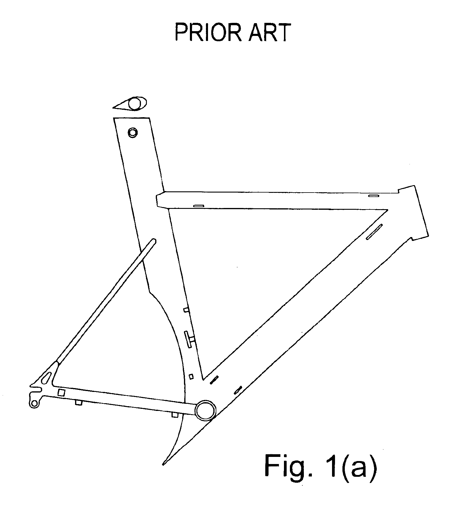
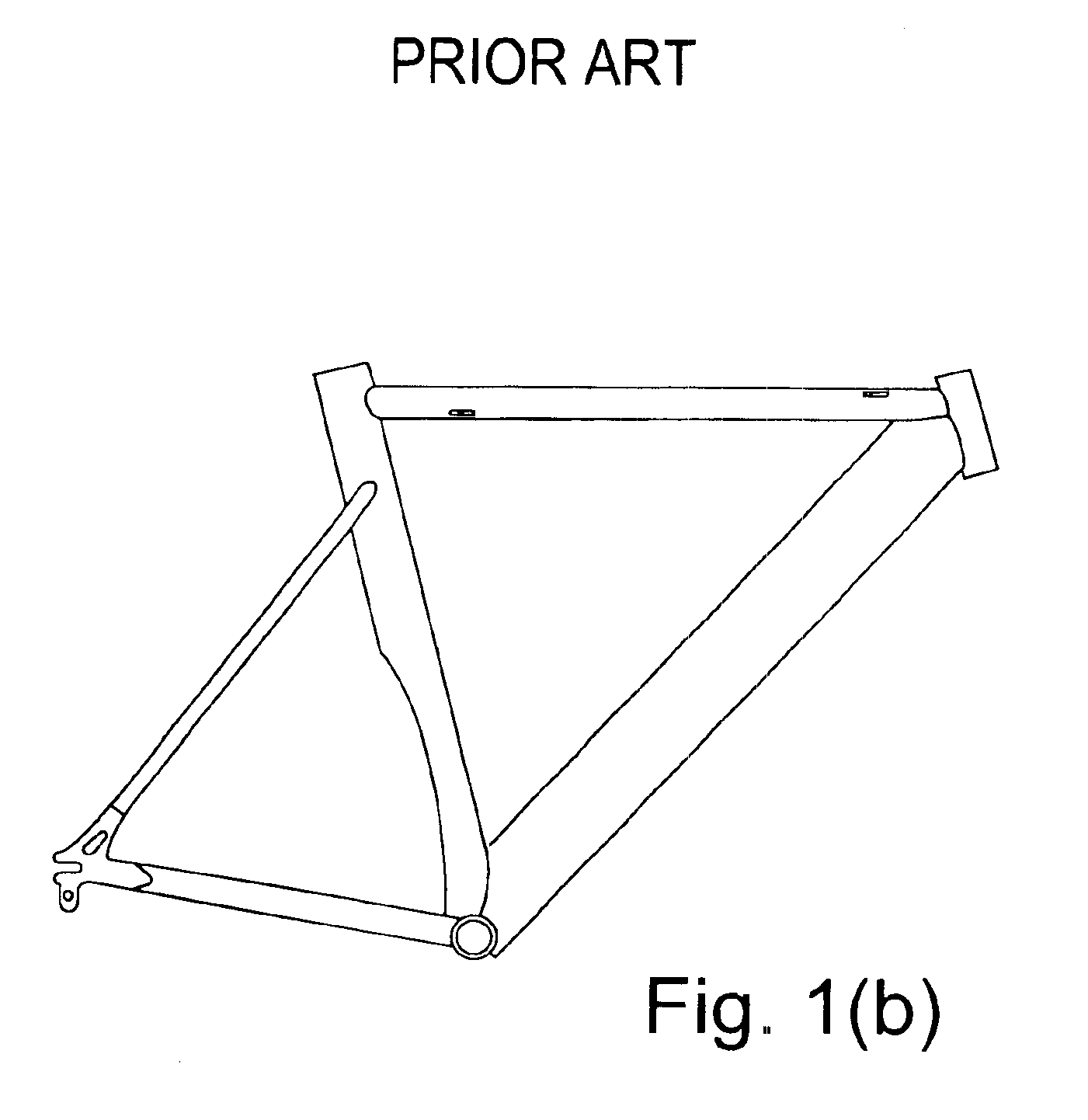
[0029]In the following description, similar features in the drawings have been given similar reference numerals.

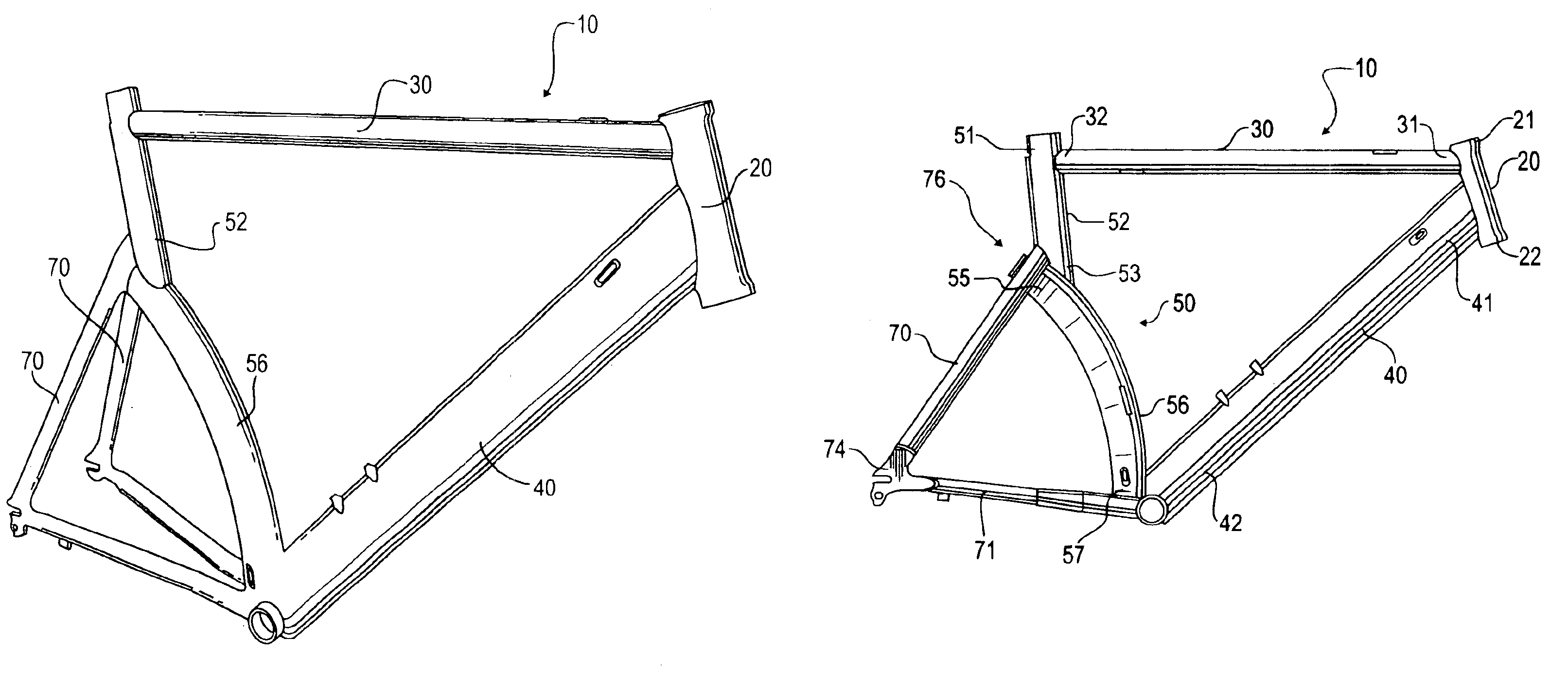
[0030]Features of the bicycle frame according to this invention are illustrated in FIGS. 3 through 11 and 13. Referring to FIG. 6, the bicycle frame 10 comprises a head tube 20, a top tube 30, a down tube 40 and a seat tube 50. The head tube 20 extends obliquely between its upper end 21 and its lower end 22, and forms an angle of about 0 to 30 degrees with the vertical. In a preferred embodiment of the invention, this angle is about 20 degrees. The top tube 30 is attached to the upper part 21 of the head tube at its first end 31 and extends substantially horizontally therefrom. The top tube may form an angle of about 0 to 15 degrees with the horizontal and can be sloped either upwardly or downwardly. In a preferred embodiment of the invention, this angle is 0 degree. The down tube 40 is attached at its first end 41 to the lower part of the head tube 22. The down tube exten...


PUM


Abstract

There is provided a bicycle frame comprising a first tube; a second tube extending transversely from an upper region of the first tube; a third tube extending transversely and downwardly from a lower region of the first tube, and towards the same direction as the second tube; and a two-part tube joining the respective ends of the second and third tubes, the two-part tube having a straight upper part and a curved lower part, the straight upper part being substantially vertical and the curved lower part being curved longitudinally towards the first tube such as to conform to the curvature of a bicycle wheel. The upper part of the two-part tube is adapted to receive a post member therein, and a first and a second set of tubes extend at the respective ends the two-part tube and are each attached to drop.

Description

[0001]This application is a continuation-in-part of U.S. application Ser. No. 09 / 961,041, filed Sep. 20, 2001, abandoned which claims priority to Canada application no. 2,319,985, filed Sep. 20, 2000.FIELD OF THE INVENTION[0002]The present invention relates generally to an aerodynamic bicycle frame. Particularly, the invention relates to a bicycle frame allowing for an optimal aerodynamic shielding on the upper portion of the rear wheel. More particularly, the invention relates to an aerodynamic bicycle frame to which a brake is removably attached, without reducing the aerodynamic efficiency of the frame.BACKGROUND OF THE INVENTION[0003]Conventional bicycle frames, as illustrated for example in FIG. 13 generally have a one-piece straight seat tube. Bicycle frames with a one-piece seat tube having a curved portion are also known in the art, as illustrated for example in U.S. Pat. No. 5,957,473 to Lawwill and U.S. Pat. No. 4,900,050 to Bishop et al.[0004]It has been found advantageous...

Claims


Application Information

Patent Timeline
IPC IPC(8): B62K19/00B62K19/06
CPCB62K19/06B62K19/00B62K3/04B62K19/02
Inventor VROOMEN, GERARDWHITE, PHILIP
Owner CERVELO USA INC
Why Eureka
Try Eureka