
Propeller

A technology of propellers and blades, applied in the field of propellers

Inactive Publication Date: 2007-02-07
MICHAELLA K CORP
View PDF1 Cites 5 Cited by
  • Summary
  • Abstract
  • Description
  • Claims
  • Application Information

AI Technical Summary

Problems solved by technology

[0004] A disadvantage of the two known propellers is that each design of the propeller generates high aerodynamic loads acting on it, which leads to the necessity of providing its high strength and stiffness

Method used


Image

  • Propeller
  • Propeller
  • Propeller

Examples


Embodiment Construction

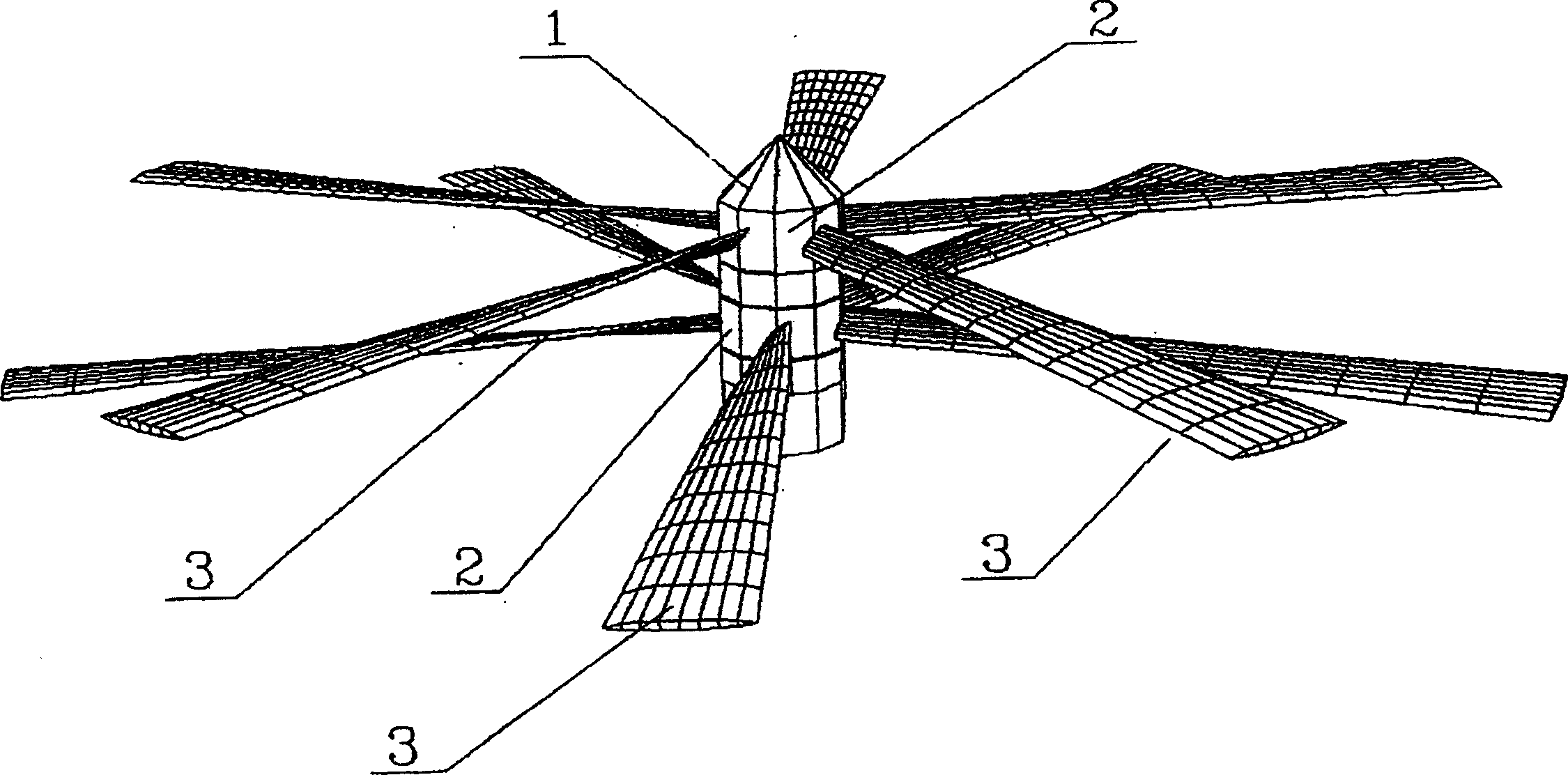
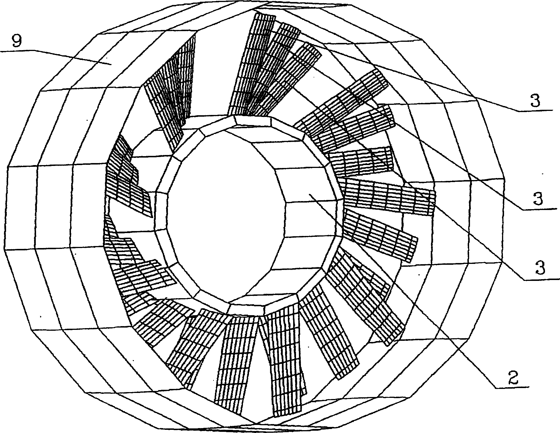
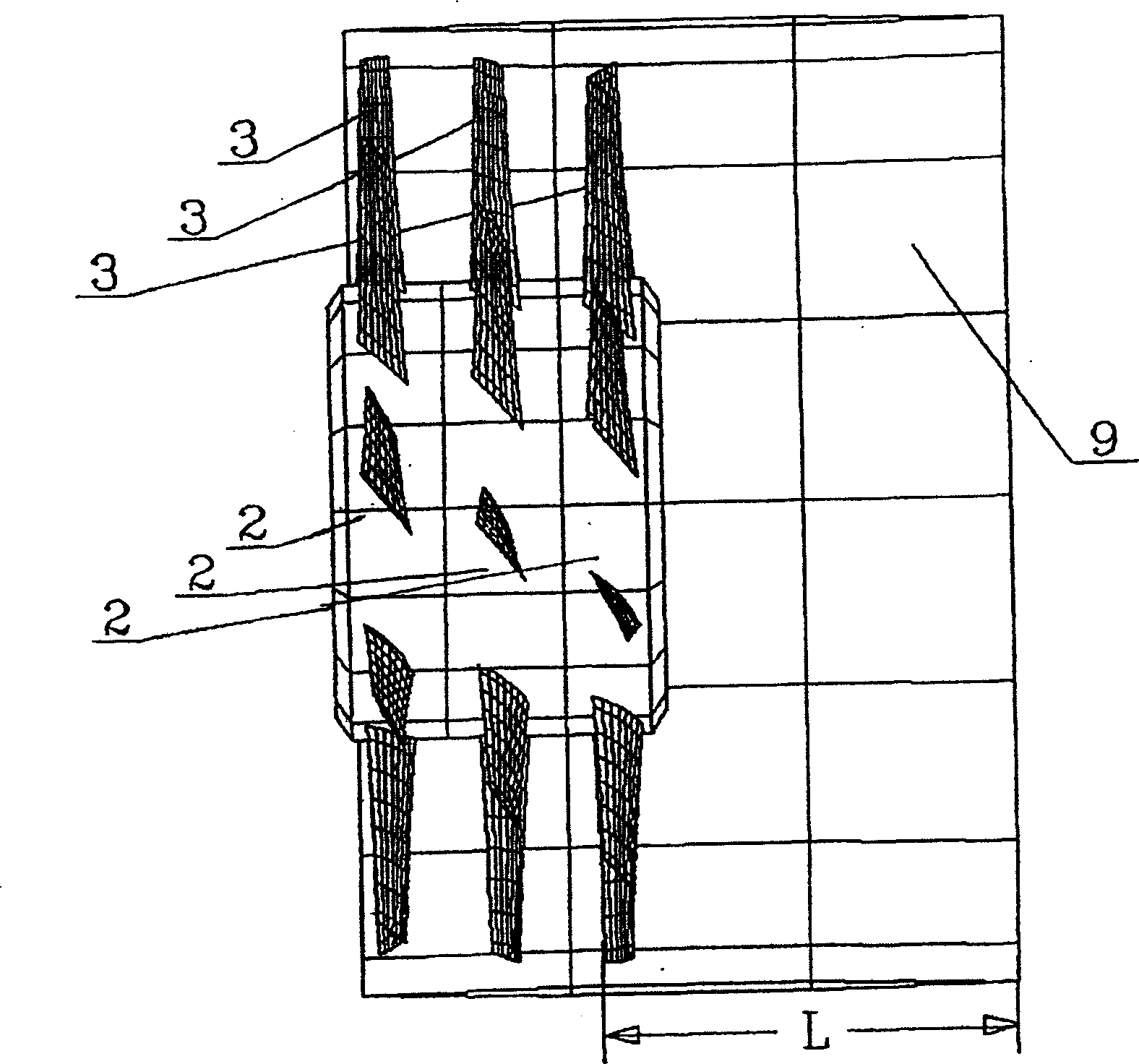
[0016] The propeller has a main shaft 1 on which at least two hubs 2 are arranged, and the main shaft 1 has blades 3 uniformly fixed on the circumference of each hub. The number of hubs with blades 3 can be different. The blades 3 on each sequential hub 2 can be fixed with the possibility of rotation in opposite directions, and with the possibility of rotation in one direction. This rotation can be performed by a motor through a drive shaft and a gear train.

[0017] Each blade 3 has a sharp front edge 4 and a sharp rear edge 5 and is configured along the extension of the blade 3 to have a maximum thickness (0.10-0.25) b of the profile, where b is the length of the local chord of the blade 3 .

[0018] In each blade 3 the maximum thickness 6 of the profile is located in the middle of each partial chord.

[0019] The profile can have different shapes, eg biconvex, wedge, rhombus. Profiles of different shapes can be formed along the extension of the blade.

[0020] Each blad...


PUM


Abstract

A propeller has a shaft 1 with at least two hubs 2 arranged on it, with blades 3 fixed on each of the hubs. Each blade 3 has sharp front and rear edges and configured along an extension of the blades with a maximum thickness of profiles (0.10-0.25)b, wherein b is a length of a local chord of the blade 3. In each of the blades 3 a maximum thickness 6 of the profile is located in a middle of each local chord and twisted relative to an axis 8, extending through a middle of local chords along the extension of the blade 3. The blades 3 can be fixed on each of the hubs 2 inclinedly to a radius of the hub 2 at an angle < 90 , which leads to a reduction of local aerodynamic resistance and reduction of aerodynamic loads. The propeller can be provided with an immovable cylindrical casing, surrounding all the blades 3 and moved out forwardly of the blades of the front hub 2 not less than by a length of the blade, which increases a value of a torque.

Description

technical field [0001] The invention relates to propellers, which can be used in the fields of aviation and special transport (thruster skids, air-supported dirigibles). Background technique [0002] Known propellers have a main shaft on which two hubs are mounted, and the main shaft has blades fixed uniformly over the circumference on each hub. The blades on the two hubs are rotationally driven in opposite directions by motors (U.S. Patent no. 2953320 U.S. Cl.: 244-12, 1960). [0003] Known propellers have a main shaft on which two hubs are mounted, and the main shaft has blades fixed uniformly over the circumference on each hub. The blades of the two hubs are rotationally driven in opposite directions by motors (RU patent no. 2062246, IPC: B64C29 / 00, 1996). [0004] A disadvantage of the two known propellers is that each design of the propeller generates high aerodynamic loads acting on it, which leads to the necessity of providing its high strength and rigidity. Conte...

Claims


Application Information

Patent Timeline
Patent Type & Authority Applications(China)
IPC IPC(8): B64C11/48B64C11/18B64C11/00
CPCB64C11/18B64C11/48B64C11/001
Inventor A·I·阿卡罗A·M·泽林斯基M·M·梅德维德夫
Owner MICHAELLA K CORP
Learn More