Head-rest arrangement

a headrest and headrest technology, applied in the direction of vehicle safety arrangments, pedestrian/occupant safety arrangements, chairs, etc., can solve the problems of whiplash injuries, neck strain, whiplash injuries of passengers in vehicles,

Inactive Publication Date: 2005-05-10
AUTOLIV DEV AB
View PDF5 Cites 122 Cited by
  • Summary
  • Abstract
  • Description
  • Claims
  • Application Information

AI Technical Summary

Benefits of technology

[0006]The present invention seeks to pr

Problems solved by technology

It is known that if a motor vehicle is involved in a rear impact, the occupant of a seat within the vehicle may suffer fr

Method used


Image

  • Head-rest arrangement
  • Head-rest arrangement
  • Head-rest arrangement

Examples


Embodiment Construction

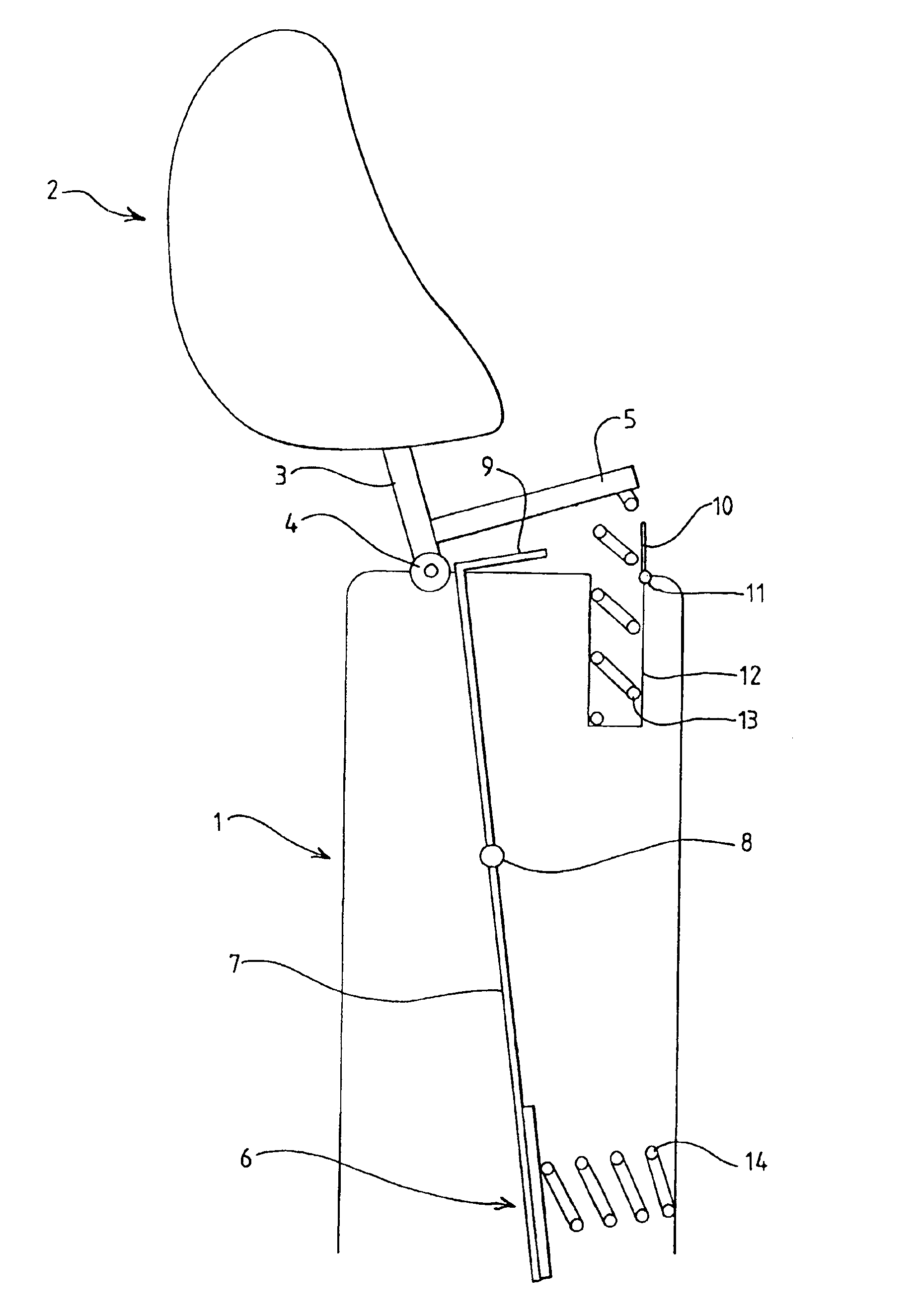
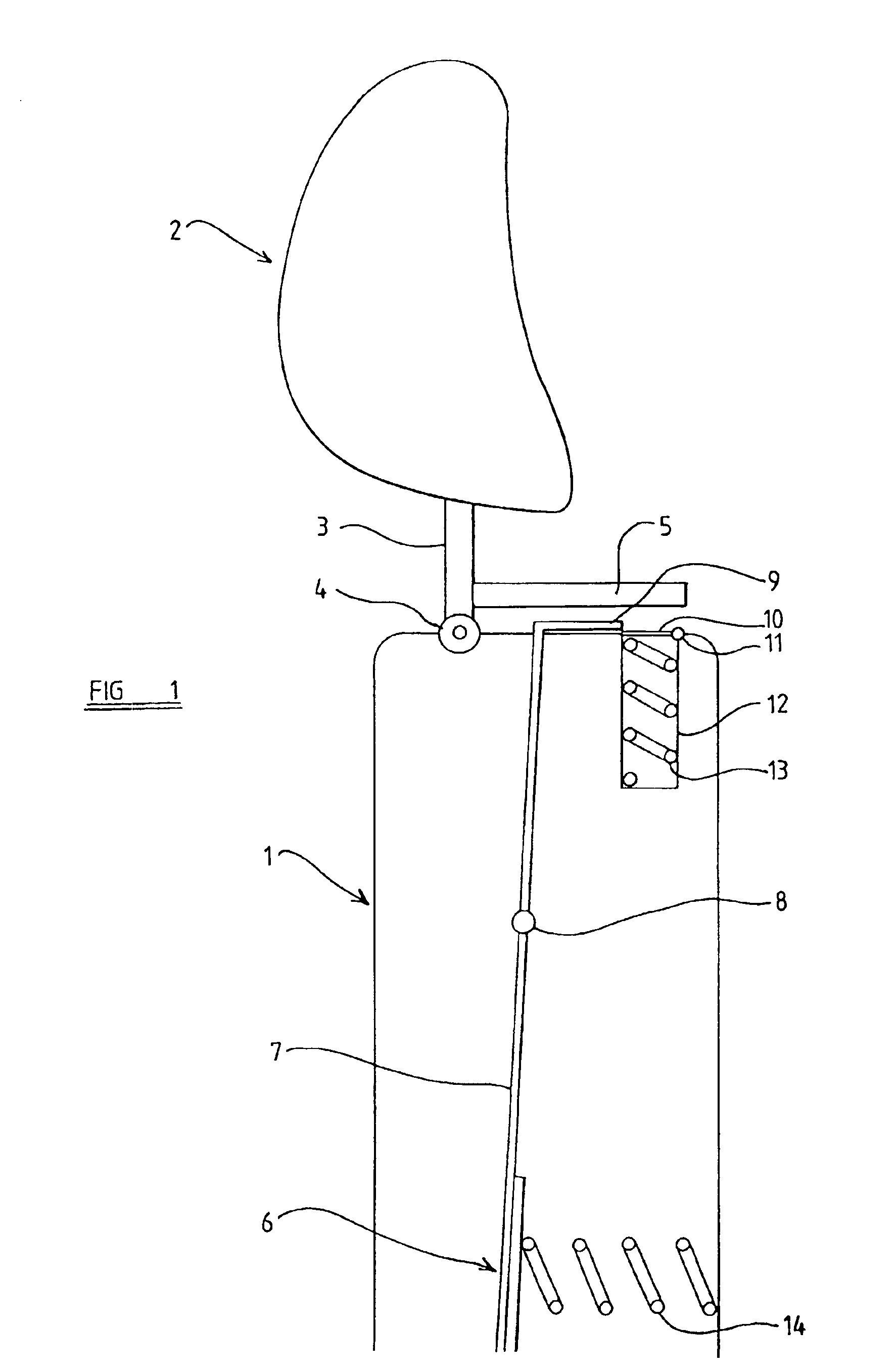
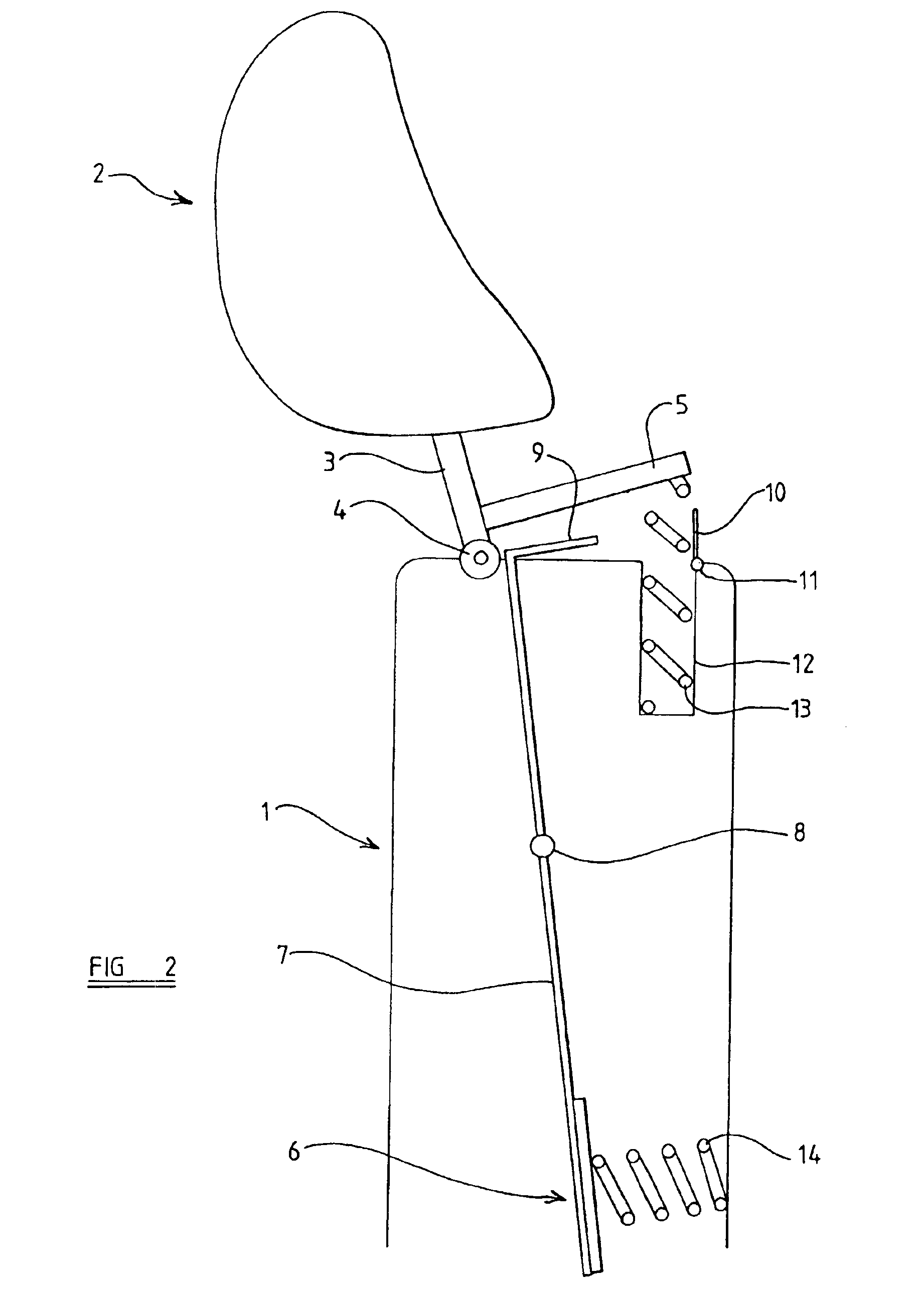
[0027]Referring initially to FIG. 1 of the accompanying drawings, a vehicle seat has a seat-back 1 which is provided with a head-rest 2. The head-rest 2 is mounted on one or more support rods 3. The support rods are pivotally connected to the upper part of the head-rest by a pivotal connection 4, so that the entire head-rest can move pivotally about a horizontal axis substantially aligned with the pivotal connection 4, between an initial upright position and a final position which is forward of the initial position. The support rods 3 are provided adjacent the lower ends thereof with a rearwardly extending initially horizontal actuating plate 5.

[0028]Mounted within the seat-back 1 is a pressure responsive element in the form of a pressure plate 6 which is located at a point substantially co-aligned with the center of the torso of the occupant of the seat. Pressure plate 6 is supported by a support arm 7 which is mounted for pivotal movement about a horizontal pivot axis 8 and is loc...


PUM


Abstract

A head-rest arrangement for a vehicle seat includes a head-rest mounted in position on a vehicle seat so that it can move forwardly from an initial position to a final position. A spring mechanism is provided to move the head-rest. A release mechanism is actuated by movement of a pressure responsive element within the back of the seat to initially prevent operation of the spring mechanism, and to release the spring mechanism when pressure is applied during a rear impact.

Description

CROSS REFERENCE TO RELATED APPLICATION[0001]This application claims the benefit of related British patent application Serial No. 0302088.0, filed Jan. 29, 2003.BACKGROUND OF THE INVENTION[0002]The present invention relates to a head-rest arrangement, and more particularly relates to a head-rest arrangement for use in a motor vehicle seat.[0003]It is known that if a motor vehicle is involved in a rear impact, the occupant of a seat within the vehicle may suffer from so-called “whiplash” injuries.[0004]When a vehicle is involved in a rear impact, the chassis of the vehicle is suddenly accelerated from a stationary condition or a low speed, to a relatively high speed. The seats within the vehicle, which are typically securely fastened to the chassis, thus experience an equivalent rapid acceleration. That rapid acceleration is imparted to the parts of the occupant of the seat that are in contact with the seat; namely, the posterior and the lower part of the torso. The head of the occupa...

Claims


Application Information

Patent Timeline
IPC IPC(8): B60N2/48A47C7/44A47C7/38B60N2/42
CPCB60N2/4885B60N2/4852B60N2/888B60N2/853
Inventor SVANTESSON, ANDERS
Owner AUTOLIV DEV AB
Why Eureka
Try Eureka