Deicing device for wind turbine blades

Active Publication Date: 2005-05-10
GENERAL ELECTRIC CO
View PDF3 Cites 218 Cited by
  • Summary
  • Abstract
  • Description
  • Claims
  • Application Information

AI Technical Summary

Problems solved by technology

However, the recent efforts have not effectively addressed the loss of availability.
Icing frequently adversely affects performance of the wind turbines during winter seasons.
At times, icing is so severe that it prevents the turbines from producing power despite the existen

Method used


Image

  • Deicing device for wind turbine blades
  • Deicing device for wind turbine blades
  • Deicing device for wind turbine blades

Examples


Embodiment Construction

[0014]Deicing devices and methods for wind turbine blades are described herein. In the following description, numerous details are set forth to provide a more thorough explanation of the present invention. It will be apparent, however, to one skilled in the art, that the present invention may be practiced without these specific details. In other instances, well-known structures and devices are shown in block diagram form, rather than in detail, in order to avoid obscuring the present invention.

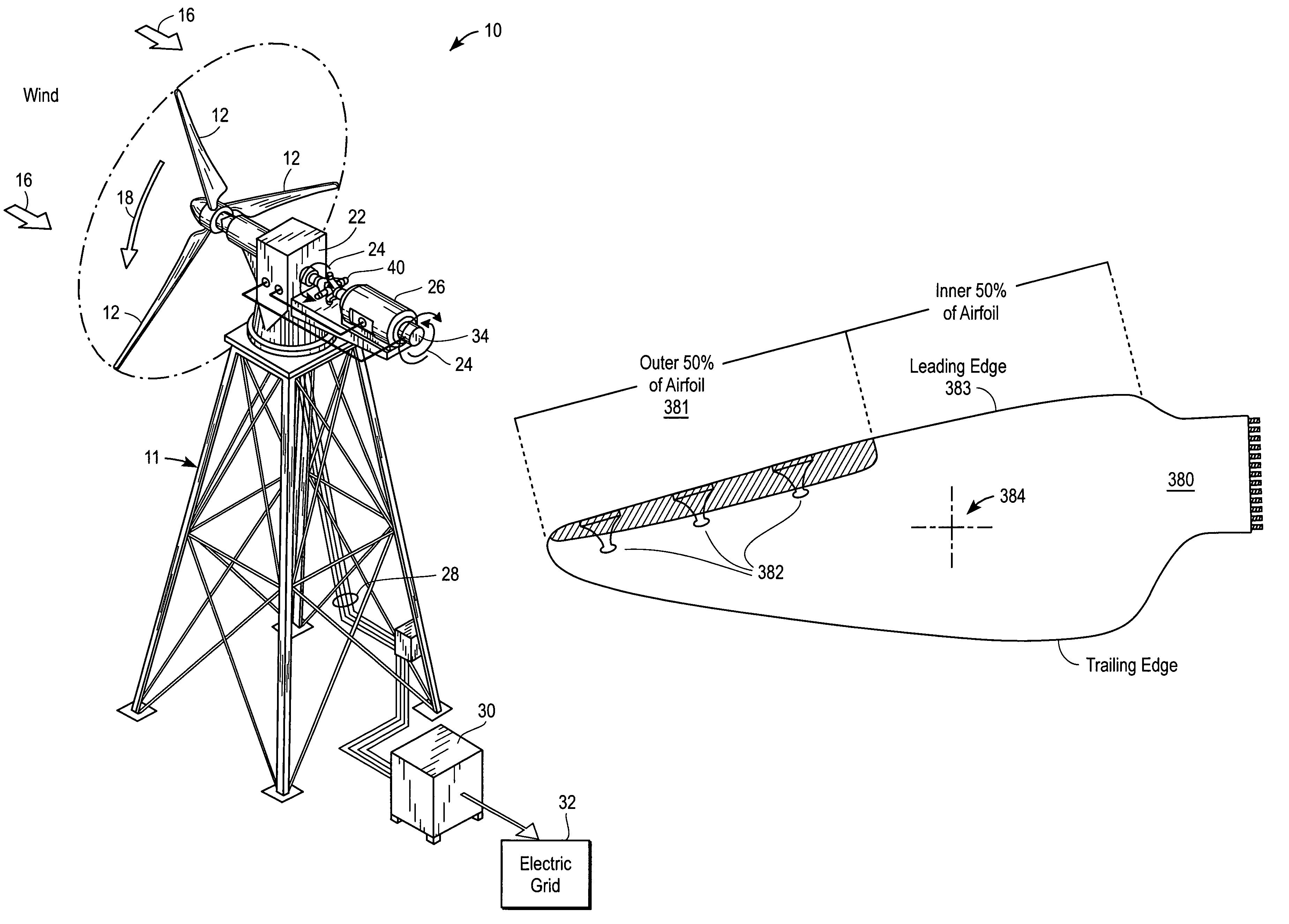
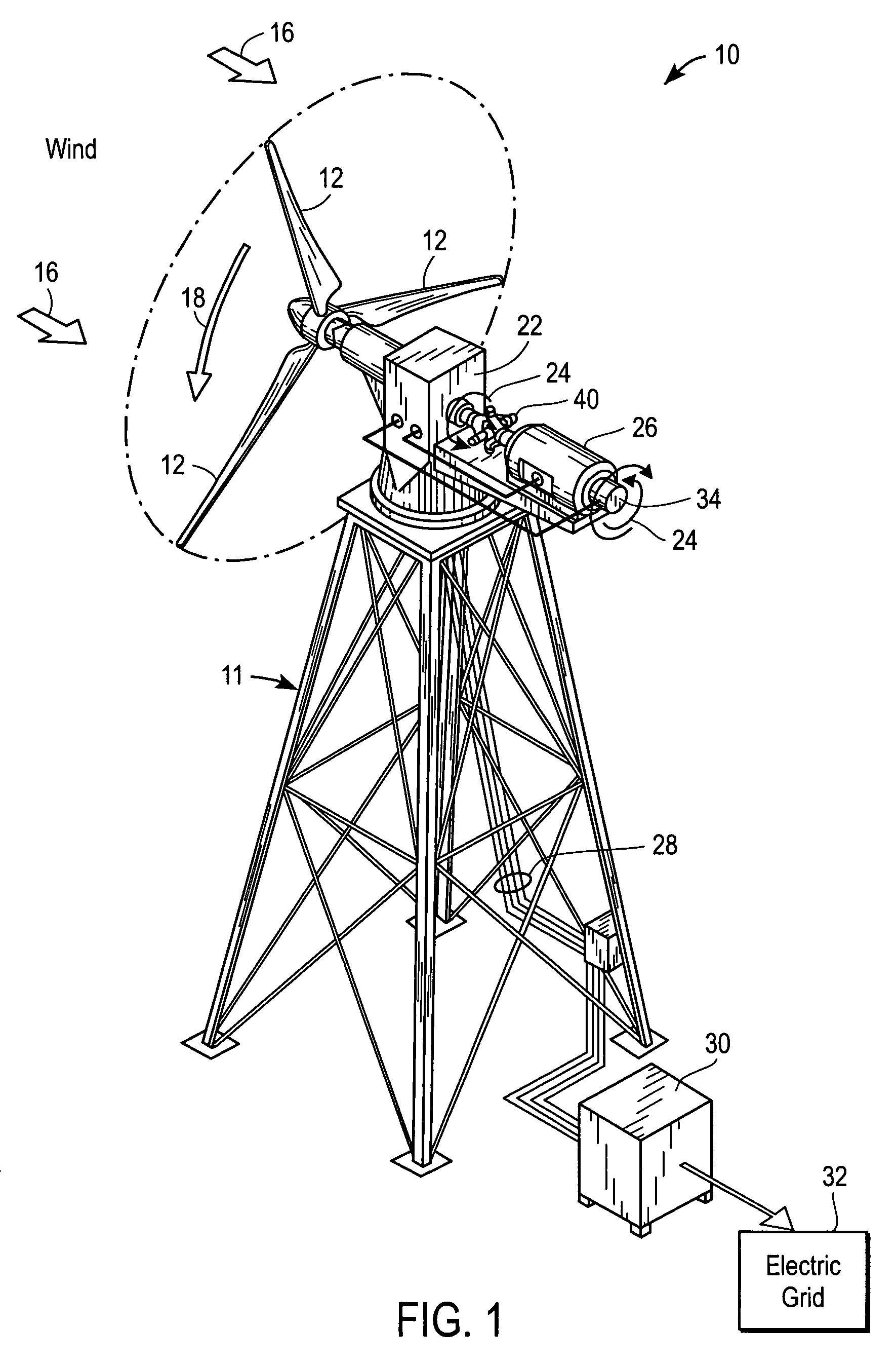
[0015]FIG. 1 is a perspective view of an embodiment of a wind turbine generator. Referring to FIG. 1, an exemplary wind turbine is indicated generally at 10, mounted on a pedestal 11. Wind turbine 10 has one or more blades 12 connected to a shaft 14. When wind blows from the direction 16, the blades 12 and the shaft 14 rotate in the direction of arrow 18. However, in other embodiments, the rotational direction may be in the opposite direction from the direction of arrow 18 with equivalent but ...


PUM


Abstract

Methods and Apparatuses for deicing a wind turbine blade are described herein. In one embodiment, an exemplary process includes detecting an icy condition on a wind turbine blade and causing at least a portion of the wind turbine blade to vibrate, causing the ice built up on the wind turbine blade to break off.

Description

FIELD OF THE INVENTION[0001]The present invention relates generally to wind turbines. More particularly, this invention relates to a deicing device for wind turbine blades.BACKGROUND OF THE INVENTION[0002]Wind turbines provide a primary source of energy that can be converted into electricity and supplied to utility power grids. Conversion of wind energy to electrical energy is accomplished in a wind turbine by driving an electrical generator, commonly an AC induction generator. Recently, wind turbines have received increased attention as environmentally safe and relatively inexpensive alternative energy sources. With this growing interest, considerable efforts have been made to develop wind turbines that are reliable, efficient, and have increased availability.[0003]However, the recent efforts have not effectively addressed the loss of availability. Icing frequently adversely affects performance of the wind turbines during winter seasons. At times, icing is so severe that it prevent...

Claims


Application Information

Patent Timeline
IPC IPC(8): F03D11/00
CPCF03D11/0025Y02E10/722F03D80/40Y02E10/72
Inventor THISTED, BO
Owner GENERAL ELECTRIC CO
Why Eureka
Try Eureka