
Hinged weatherproof electrical box cover

Inactive Publication Date: 2005-05-10
THOMAS & BETTS INT INC
View PDF4 Cites 91 Cited by
  • Summary
  • Abstract
  • Description
  • Claims
  • Application Information

AI Technical Summary

Problems solved by technology

Due to the varied needs for electrical power and switching, it is sometimes necessary to mount a box in a location where it will be exposed to wet conditions.

Method used


Image

  • Hinged weatherproof electrical box cover
  • Hinged weatherproof electrical box cover
  • Hinged weatherproof electrical box cover

Examples


Embodiment Construction

[0014]There will be detailed below the preferred embodiments of the present invention with reference to the accompanying drawings. Like members are designated by like reference characters in all figures.

[0015]The present invention is directed to a weatherproof cover for an electrical connector box for providing water protection to components accommodated therein without the use of a gasket, having selectively interchangeable faceplates for adaptation to a variety of electrical components and which can be utilized with a connector box mounted in either a horizontal or vertical orientation.

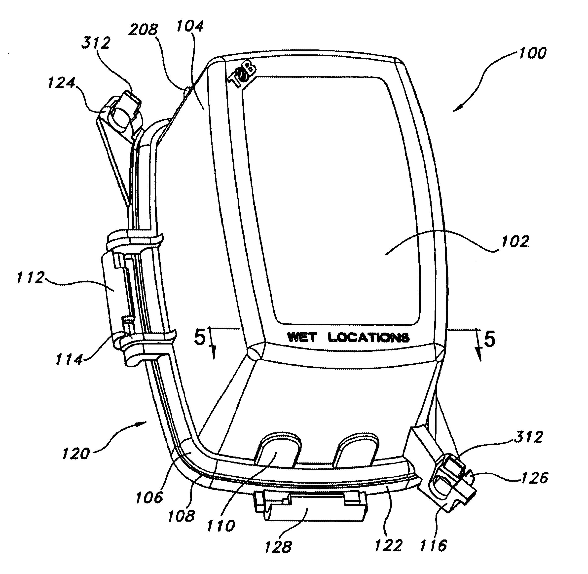
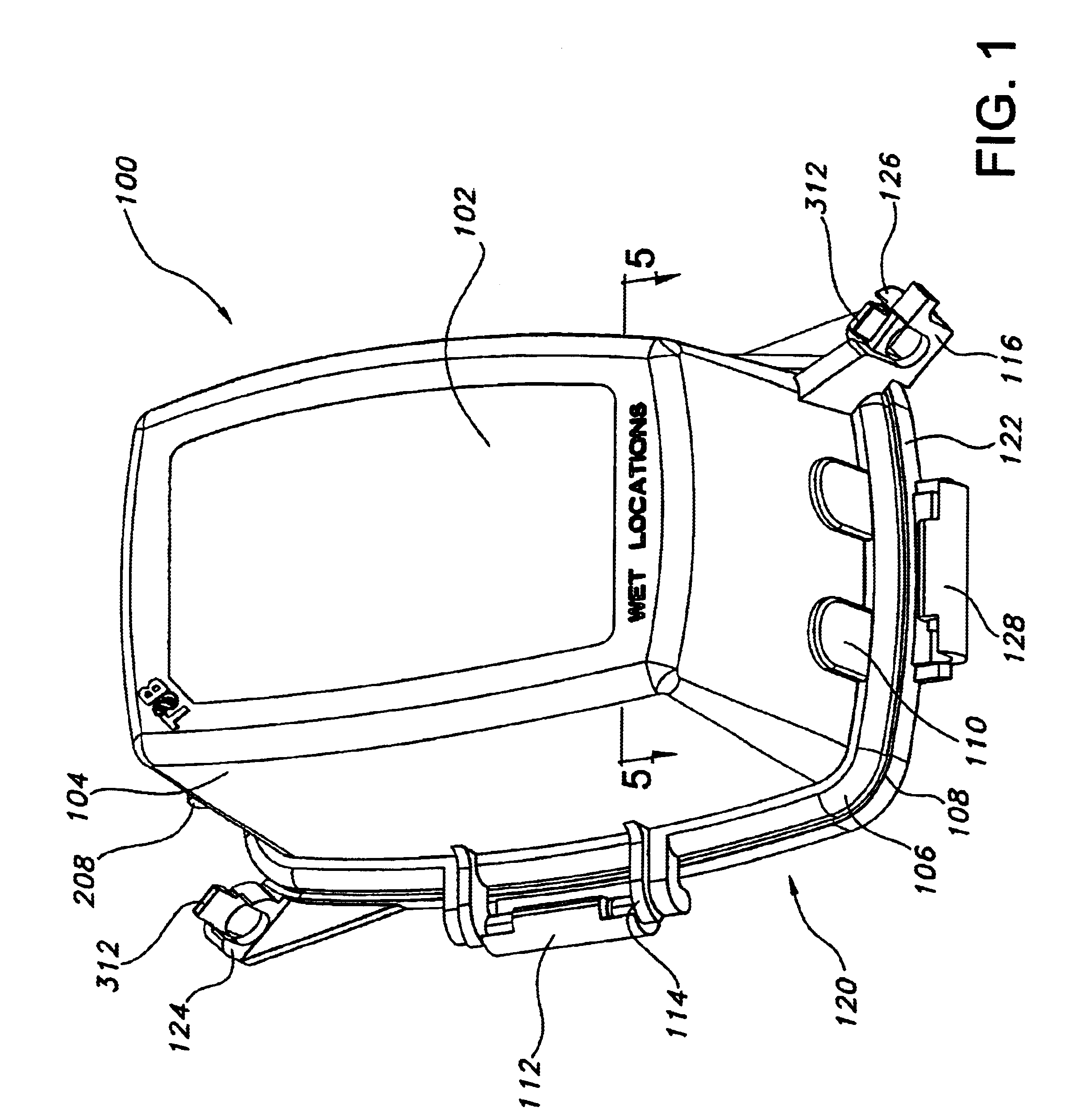
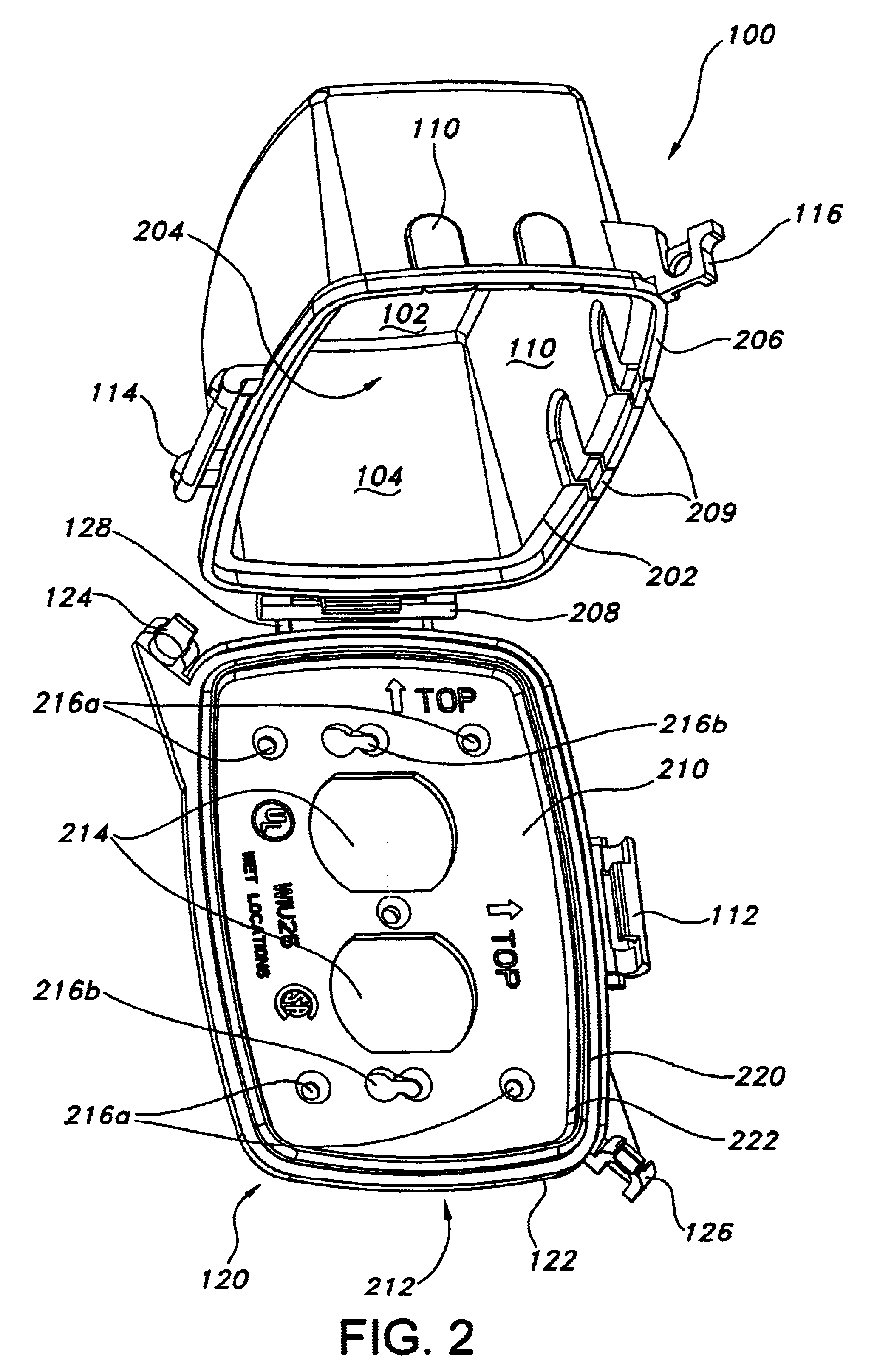
[0016]Turning now to FIG. 1, the electrical connector box cover 100 of the present invention is shown. The electrical connector box cover 100 is a generally rectangular box-like member having a substantially planar rectangular front 102 that is perimetrically bounded by an outer wall 104, that is comprised of four substantially planar side walls having two sets of substantially parallel sides. The o...


PUM


Abstract

The present invention is directed to a weatherproof electrical outlet box assembly for shielding and protecting electrical components from moisture comprising a faceplate for attaching to an outlet box, the faceplate being substantially planar, and perimetrically bounded by a substantially rectangular side edge, the faceplate having at least one aperture for receiving an electrical component and; the faceplate including a first hinge socket and a second hinge socket extending respectively from the side edge in substantially orthogonal orientation. The weatherproof electrical outlet box assembly further including a cover having a front wall, an opposed open end and a substantially rectangular perimetrical side wall therebetween defining a cover interior, the side wall having a rim bounding the open end, the cover including at least one access port through the side wall adjacent the open end for providing separate passageways into the interior of the cover; the cover including a first hinge pin and a second hinge pin extending respectively from the side wall adjacent the open end in substantially orthogonal orientation; and the cover being pivotally affixed to the faceplate by operative engagement of the hinge socket with the hinge pin of corresponding orientation and movable between an open and a closed position and wherein the hinge pin and the hinge socket that are not in operative engagement are not aligned.

Description

FIELD OF THE INVENTION[0001]This invention relates to a hinged electrical connection box cover for covering electric and / or electronic components, having a cover body, comprising a bottom and side walls, and open top defined by the said walls, wherein the cover can be closed over a selectively interchangeable faceplate, that is rigidly mounted to accommodate an electrical component and pivotally attached to the cover wherein the hinged front cover can be opened and closed whether the faceplate is oriented about either a horizontal or vertical axis, and provide weatherproof protection to the electrical component.BACKGROUND OF THE INVENTION[0002]Electrical boxes are used for a variety of applications wherein it is necessary to provide a termination point for electrical wires for splicing or connection to an electrical component. An electrical box is rigidly mounted on or in a wall in such locations to conveniently locate an electrical component. Depending on the application and locati...

Claims


Application Information

Patent Timeline
Patent Type & Authority Patents(United States)
IPC IPC(8): H02G3/14
CPCH02G3/14H02G3/088
Inventor DINH, CONG THANH
Owner THOMAS & BETTS INT INC
Learn More