Apparatus and method for re-executing pre-pit detection if pre-pits are not detected after changing reference level

a technology of pre-pit signal and reference level, which is applied in the direction of digital signal error detection/correction, instruments, recording signal processing, etc., can solve the problems of overwritten information not being stably detected, noise components of extracted wobble signal including pre-pit signals increasing, and difficult to stably perform the detection of pre-pit signals

Inactive Publication Date: 2005-05-10
PIONEER CORP
View PDF7 Cites 12 Cited by
  • Summary
  • Abstract
  • Description
  • Claims
  • Application Information

AI Technical Summary

Benefits of technology

[0012]The present invention has been made in view of the above-described problem, and has an object to provide an information recording / reproducing apparatus and pre-pit detecting method that can stably detect pre-pits to perform correct information recording even in the area, such as the emboss area, wherein the groove track is not continuously formed.

Problems solved by technology

However, within the emboss area, even when recording information with an aim to rewrite that important information illegally, since the recording groove track is formed intermittently, the overwritten information cannot correctly be reproduced.
However, there is such a problem that, since the groove track is intermittently formed within the emboss area, the noise components of the extracted wobble signal including the pre-pit signals increase, and it becomes difficult to stably perform the detection of the pre-pit signals.
For this reason, in the so-called “finalizing processing” executed at the time of ending recording of information onto the disc, the recording clock signal becomes unstable and the finalizing processing cannot be executed correctly.

Method used


Image

  • Apparatus and method for re-executing pre-pit detection if pre-pits are not detected after changing reference level
  • Apparatus and method for re-executing pre-pit detection if pre-pits are not detected after changing reference level
  • Apparatus and method for re-executing pre-pit detection if pre-pits are not detected after changing reference level

Examples


Embodiment Construction

[0038]Hereinafter, a preferred embodiment of the present invention will be explained with reference to the appended drawings.

[0039][1] Configuration of the Optical Disc

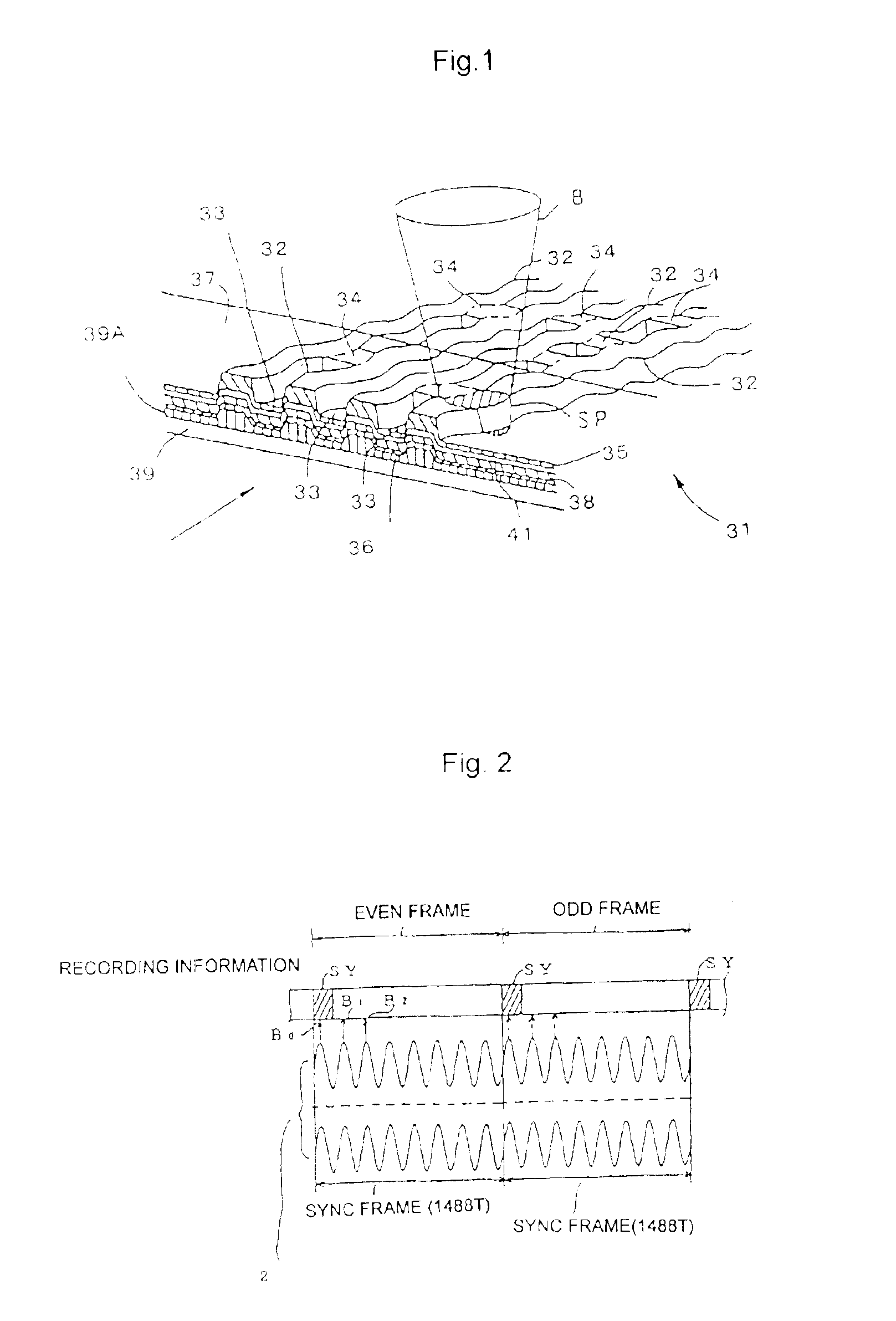
[0040]First, an explanation will be given, using FIGS. 1 and 2, of a DVD-RW serving as an optical disc on which pre-pits corresponding to the pre-information are formed and groove tracks as later described are wobbled at a prescribed frequency.

[0041]First of all, a structure of a DVD-RW will be explained with reference to FIG. 1. In FIG. 1, the DVD-RW 31 is a rewritable pigment type disc having a recording layer 41 serving as a data recording layer. The DVD-RW 31 has groove tracks 32 serving as a data recording track, and land tracks 33 serving as a guiding track for guiding, to the groove track 32, a light beam such as a laser beam which serves as a reproduction light or a recording light. The land track 33 is formed with pre-pits 34 corresponding to the pre-information. These pre-pits 34 are previously formed before...


PUM

PropertyMeasurementUnit
areaaaaaaaaaaa
frequencyaaaaaaaaaa
central frequencyaaaaaaaaaa

Abstract

An information recording/reproducing apparatus irradiates a light beam on an optical disc on which pre-pits are formed, and performs recording and/or reproduction of information with respect to the optical disc according to a recording clock produced based on a wobble signal and a pre-pit signal. When recording information onto the optical disc having the pre-pits, a light beam is radiated to thereby extract the wobble signal and pre-pit signal. Then, according to the wobble signal and the pre-pit signal, a recording clock signal is produced, and information is recorded based on the recording clock signal. When producing a pre-pit signal, a push-pull signal is produced from the reflected light from the optical disc, and this signal is compared with a reference level to thereby detect a pre-pit. Here, when a pre-pit is not detected, the reference level is changed and the detection processing of the pre-pits is executed again.

Description

BACKGROUND OF THE INVENTION[0001]1. Field of Invention[0002]The present invention belongs to a technical field of an information recording / reproducing apparatus by which information is recorded on a recordable optical disc and is reproduced therefrom. More particularly, the invention relates to a technique for stably detecting pre-pits provided on the optical disc.[0003]2. Description of Related Art[0004]As an information recording medium on which information is additionally writable or rewritable, there is known a disc such as a CD-R (Compact Disc-Recordable), a DVD-R (DVD-Recordable), a DVD-RW (DVD-Rewritable), etc.[0005]In order to record information on its non-recorded area, the above disc is formed with groove tracks (recording tracks) that are slightly wobbled in the radial direction of the disc. The groove track is formed on the disc in correspondence with a wobble signal obtained by frequency-modulating a carrier wave of a prescribed frequency by pre-information indicating t...

Claims


Application Information

Patent Timeline
Patent Type & Authority Patents(United States)
IPC IPC(8): G11B27/19G11B20/14G11B27/24G11B20/12G11B7/005G11B7/00G11B7/007
CPCG11B7/005G11B7/0053G11B20/1217G11B20/1403G11B27/24G11B7/00745G11B7/24082G11B2220/2562G11B2020/1274G11B2020/1275G11B2020/1287G11B2020/1298G11B2220/215G11B2220/216
Inventor YANAGAWA, NAOHARUTANAKA, JUNJIAKABANE, SHINSUGIYAMA, TAKAKAZU
Owner PIONEER CORP
Why Eureka
Try Eureka