
Distributing packets among multiple tiers of network appliances

Inactive Publication Date: 2005-05-10
CISCO TECH INC
View PDF44 Cites 111 Cited by
  • Summary
  • Abstract
  • Description
  • Claims
  • Application Information

AI Technical Summary

Benefits of technology

[0021]These and other features and advantages of the present invention will be presented in more detail in the following spe

Problems solved by technology

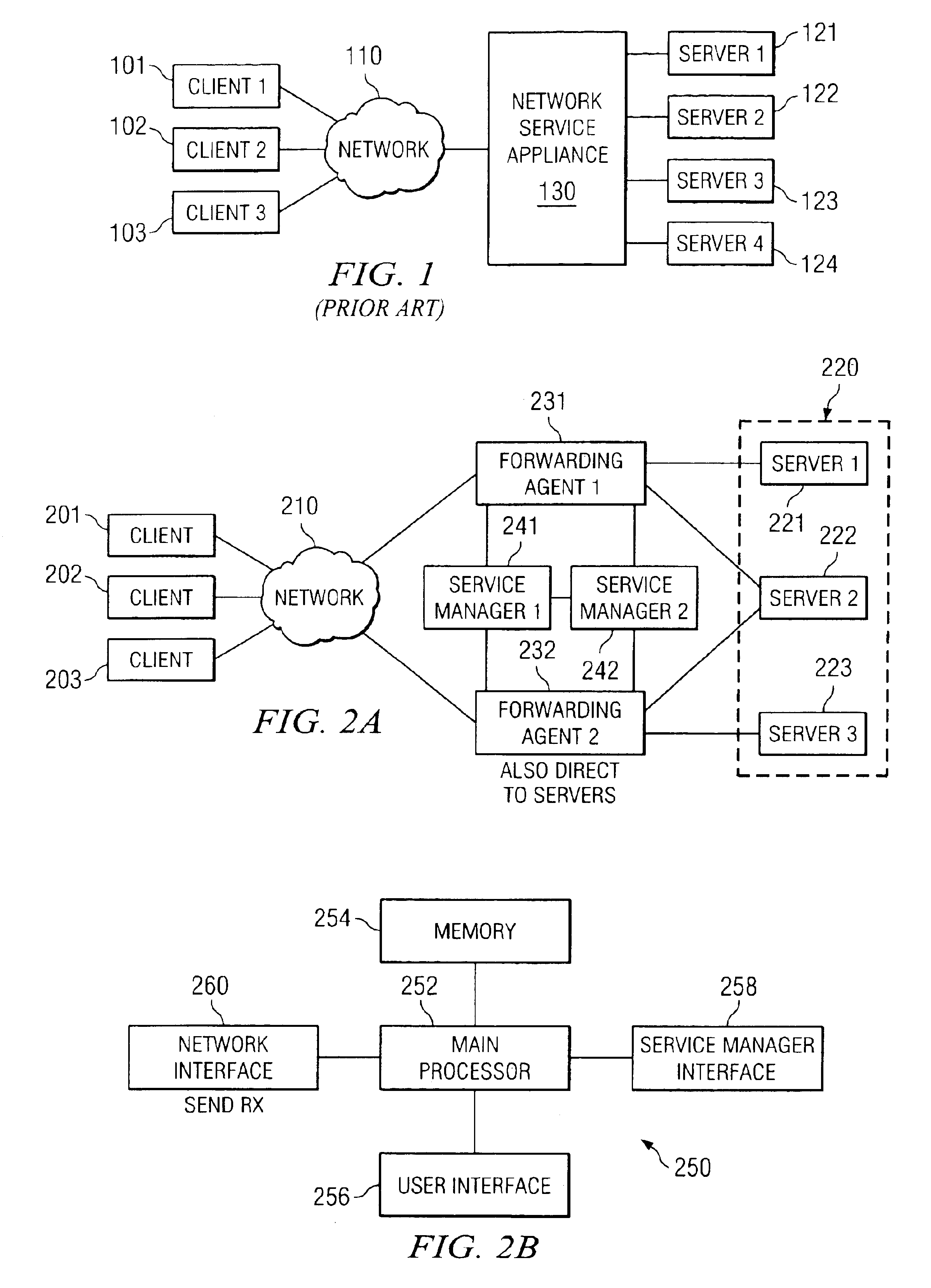
There are several disadvantages to this arrangement.
First, it is difficult to add additional network service appliances when the first network service appliance becomes overloaded because the physical connections of the network must be rerouted.
Likewise, it is difficult to replace the network service appliance with a back up network service appliance when it fails.
Since all packets pass through the network service appliance on the way to the servers, the failure of the network service appliance may prevent any packets from reaching the servers and any packets from being sent by the servers.
Such a single point of failure is undesirable.
Furthermore, as networks and internetworks have become increasingly complex, multiple services may be required for a single network and inserting a large number of network service appliances into a network in places where they can intercept all relevant packet flows may be impractical.
Although network service appliances have facilitated the development of scalable server architectures, the problem of scaling network service appliances themselves and distributing their functionality across multiple platforms has been largely ignored.
Traditional multiprocessor systems have relatively low scalability limits due to contention for shared memory and I / O.
In either case, this requires downtime for the entire machine.
Spreading users across multiple independent systems can result in wasted capacity on some systems while others are overloaded.
Individual application instances or machines can fail (or be taken down for maintenance) without shutting down service to end-users.
Users on the other systems are completely unaffected except for the additional load caused by services provided to some portion of the users that were formerly on the failed system.

Method used


Image

  • Distributing packets among multiple tiers of network appliances
  • Distributing packets among multiple tiers of network appliances
  • Distributing packets among multiple tiers of network appliances

Examples


Embodiment Construction

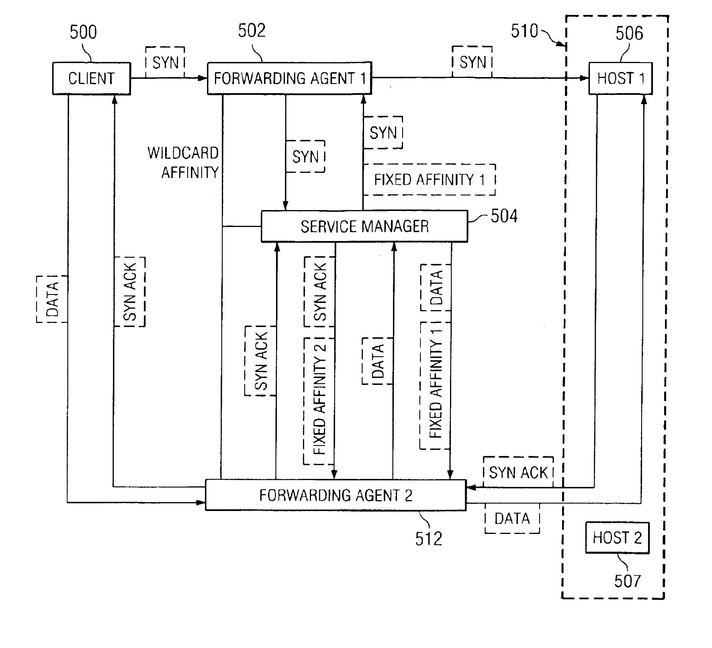
[0067]A detailed description of a preferred embodiment of the invention is provided below. While the invention is described in conjunction with that preferred embodiment, it should be understood that the invention is not limited to any one embodiment. On the contrary, the scope of the invention is limited only by the appended claims and the invention encompasses numerous alternatives, modifications and equivalents. For the purpose of example, numerous specific details are set forth in the following description in order to provide a thorough understanding of the present invention. The present invention may be practiced according to the claims without some or all of these specific details. For the purpose of clarity, technical material that is known in the technical fields related to the invention has not been described in detail in order not to unnecessarily obscure the present invention.

[0068]FIG. 2A is a block diagram of a network architecture that provides network services without...


PUM


Abstract

A network is disclosed that includes a first tier of forwarding agents connected to a first tier of network devices. A second tier of forwarding agents is connected to a second tier of network devices. A service manager is configured to receive a packet from one of the forwarding agents; determine the tier of the forwarding agent; and send an instruction to the forwarding agent directing the forwarding agent to forward the packet to a network device connected to the tier of forwarding agents that includes the forwarding agent.

Description

CROSS REFERENCE TO RELATED APPLICATIONS[0001]This Continuation application claims priority to U.S. patent application Ser. No. 09 / 346,634, filed Jul. 2, 1999 now U.S. Pat. No. 6,628,654, entitled DISPATCHING PACKETS FROM A FORWARDING AGENT USING TAG SWITCHING which is incorporated herein by reference for all purposes; and co-pending U.S. patent application Ser. No. 09 / 247,124, filed Jul. 2, 1999 entitled CASCADING MULTIPLE SERVICES ON A FORWARDING AGENT which is incorporated herein by reference for all purposes; and co-pending U.S. patent application Ser. No. 09 / 347,111, filed Jul. 2, 1999 entitled LOAD BALANCING USING DISTRIBUTED FORWARDING AGENTS WITH APPLICATION BASED FEEDBACK FOR DIFFERENT VIRTUAL MACHINES which is incorporated herein by reference for all purposes; and co-pending U.S. patent application Ser. No. 09 / 347,428, filed Jul. 2, 1999 entitled GATHERING NETWORK STATISTICS IN A DISTRIBUTED NETWORK SERVICE ENVIRONMENT which is incorporated herein by reference for all purpo...

Claims


Application Information

Patent Timeline
IPC IPC(8): H04L29/06H04L29/12H04L12/46H04L12/56H04L29/08
CPCH04L12/4633H04L29/06H04L29/12009H04L29/12783H04L45/00H04L45/50H04L63/0218H04L63/0254H04L67/1002H04L61/35H04L69/329H04L67/025H04L67/02H04L61/00H04L67/1001H04L45/76H04L45/243H04L9/40
Inventor ALBERT, MARKBATZ, ROBERTGRAY, RICHARDMCGUIRE, JACOB MARKMENDITTO, LOUISO'ROURKE, CHRISTIWARI, PRANAVTSANG, TZU-MING
Owner CISCO TECH INC
Learn More