Stabilizer bar for independently suspended beam structure

a technology of stabilizer bar and beam structure, which is applied in the direction of vehicle springs, endless track vehicles, transportation and packaging, etc., can solve the problems of unsatisfactory structures for off-road use, no structure has been developed that permits each beam to be independently suspended, and none of the suspension systems known in the art and described hereinbefore are acceptable for use on muvs, etc., to reduce or minimize the problem and reduce the body roll experienced

Inactive Publication Date: 2005-05-17
HONDA MOTOR CO LTD
View PDF37 Cites 15 Cited by
  • Summary
  • Abstract
  • Description
  • Claims
  • Application Information

AI Technical Summary

Benefits of technology

This patent describes an improvement to a suspension system on a half-track MUV (Multiple Use Vehicle) designed to reduce issues with existing systems. Specifically, it focuses on reducing bodily roll when driving over uneven terrain.

Problems solved by technology

The technical problem addressed in this patent is the lack of an effective suspension system for a half-tracked Multi-Use Vehicle (MUV), specifically designed to reduce body roll while driving over uneven terrains. Existing solutions have proven unsuitable for the challenges presented by off-road operations, resulting in poor rider comfort and reduced efficiency of the vehicle.

Method used


Image

  • Stabilizer bar for independently suspended beam structure
  • Stabilizer bar for independently suspended beam structure
  • Stabilizer bar for independently suspended beam structure

Examples


Embodiment Construction

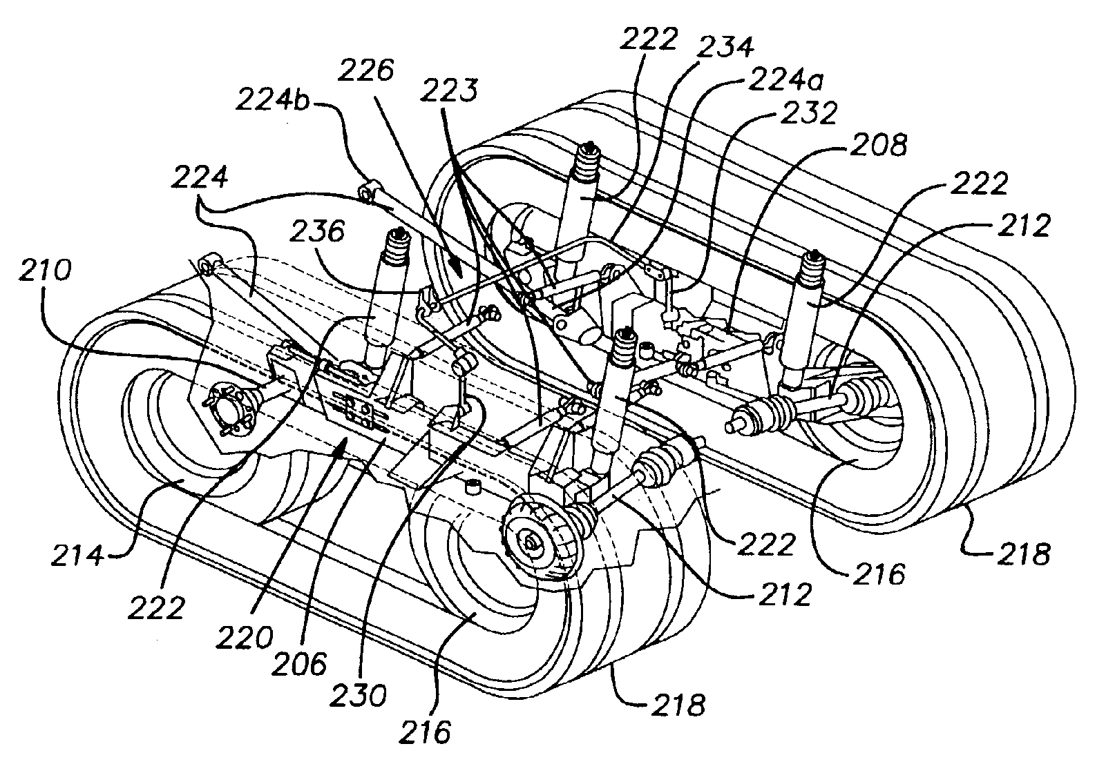
[0024]The present invention relates to a suspension system for a half-track vehicle. Initially, it is noted that the drawings are not to scale, but will be more easily understood by a person of ordinary skill in the art than drawings from another perspective or drawings shown in proper proportion. It is further noted that the drawings do not show any other structures attached to the vehicle, nor do they show any structures necessary for the functioning of the vehicle that are not directly related to the suspension structure disclosed. Accordingly, the vehicle shown in the drawing figures may not be functional without the other parts, such as a drive train and the like. However, any drive train that may be used in connection with the present structure is relatively conventional in nature. A person of ordinary skill in the art can easily adapt a known MUV drive train for use in connection with the present vehicle. Further, as the drawings only depict the rear portion of the vehicle, t...


PUM


Abstract

A half-track multi-use vehicle having an independent suspension system that reduces body roll during operation in rough or sloping terrain. The vehicle includes a frame, a pair of beams that each holds mid and rear wheels, and a suspension system extending between the each beam and the frame. The suspension system includes a plurality of cushions and a stabilizer bar. The stabilizer bar is secured to each beam at a predetermined position between the mid and rear wheels. The predetermined position is selected such that each wheel's wheel rate, which is the combined spring rate contributed by an associated cushion and the stabilizer bar, is equal.

Description


Claims


Application Information

Patent Timeline
Owner HONDA MOTOR CO LTD
Why Eureka
Try Eureka