Articulation of suspension in an independently suspended beam structure

a beam structure and independent technology, applied in the field of vehicle suspension systems, can solve the problems of unsatisfactory structures for off-road use, no structure has been developed that permits each beam to be independently suspended, and the vehicle is traveling over large objects such as logs, so as to facilitate climbing of obstacles, reduce or minimize problems, and reduce impact

Inactive Publication Date: 2005-01-11
HONDA MOTOR CO LTD
View PDF35 Cites 36 Cited by
  • Summary
  • Abstract
  • Description
  • Claims
  • Application Information

AI Technical Summary

Benefits of technology

The present invention is directed toward an improved suspension system adapted for a multi rear axle MUV vehicle that reduces or minimizes the problems in the art. The present invention is further directed toward an MUV suspension that reduces impacts experienced when the vehicle traverses changes in elevation during off-road operation. The present invention is also directed toward an MUV suspension that facilitates climbing of obstacles encountered during operation of the vehicle in an off-road setting.
In further accordance with the present invention, the first cushions have a suspension stroke that is larger than the suspension stroke of the second cushions. Accordingly, when the vehicle rides over a step or drop-off, the first wheels associated with the first cushions strike the ground sequentially before the rear wheels, leading to improved ride conditions.

Problems solved by technology

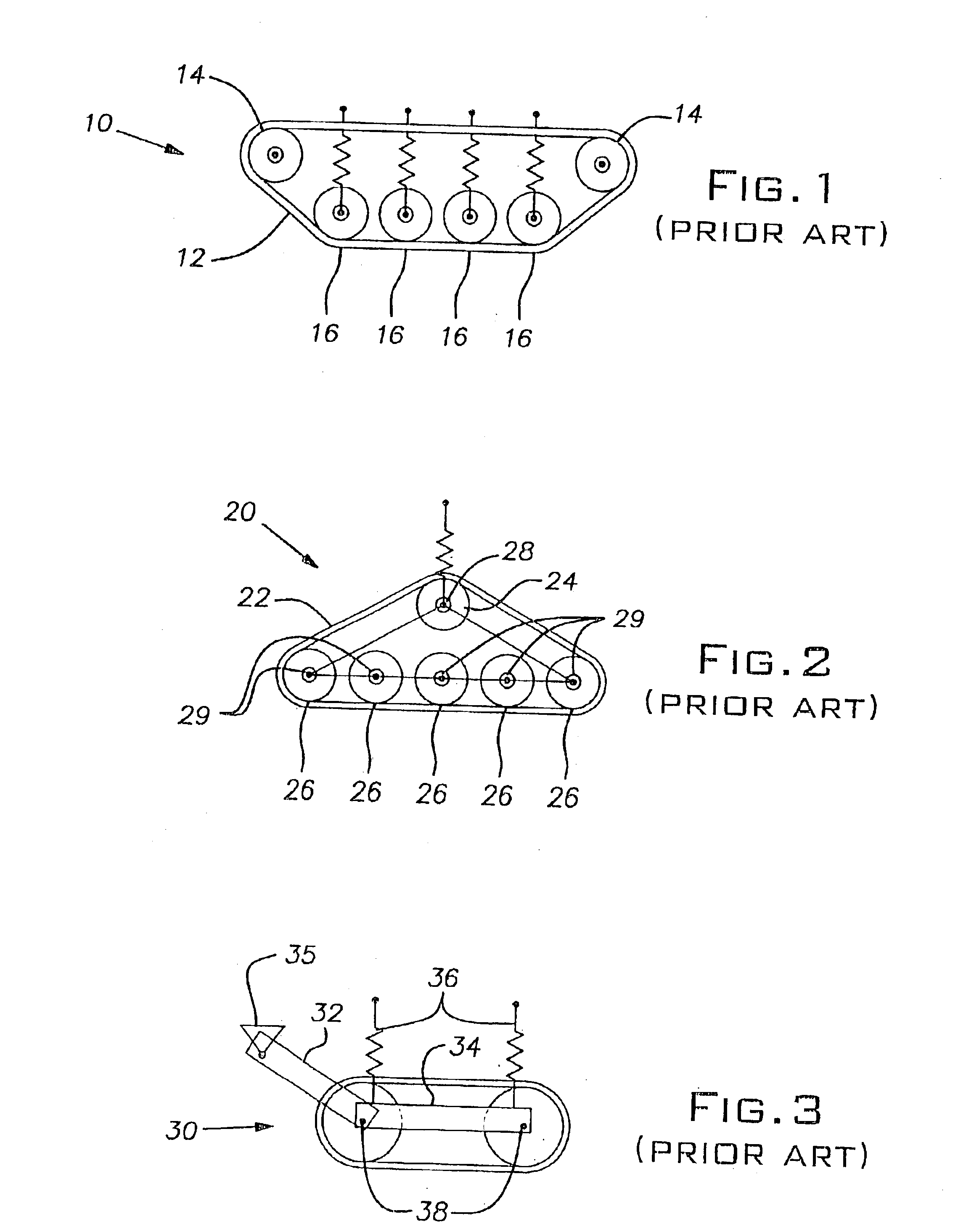
Such structures are unsatisfactory for use in an off-road setting.
However, no structure has been developed that permits each beam to be independently suspended.
Further, one of the problems to be solved with off-road vehicles is that of travel over large objects, such as logs.
However, the use of low pressure tires is not desirable for use with a tracked vehicle.
If a low pressure tire is used and the tire deforms, the track tends to have an increased amount of slack at the time of deformation, substantially increasing the risk of the track slipping off the tires.
It is inconvenient to attempt to reinstall a track that has become disengaged from the tires, particularly in an off-road setting.
Unfortunately, the use of such a tire creates a reduced amount of surface area contact between the vehicle and the obstacle, which causes the track to slip against the obstacle and prevents the vehicle from passing over the obstacle.
Therefore, in the prior art a high pressure tire is known to be undesirable.
An additional problem is common among three or more axle vehicles, namely, poor ride performance when a vehicle falls off of an obstacle or step.
However, the rear suspension structure does not absorb the shock as well.
None of the suspension systems known in the art and described hereinbefore is acceptable for use on an MUV.
Specifically, none of the known systems provides an independent suspension for a multi-rear axle vehicle wherein the vehicle is adapted to traverse drop-offs or steps with reduced shock to the vehicle and the occupants.
Moreover, none of the known systems provide an independent suspension for a half-tracked vehicle that is adapted to traverse obstacles, such as logs, ruts, and rocks.

Method used


Image

  • Articulation of suspension in an independently suspended beam structure
  • Articulation of suspension in an independently suspended beam structure
  • Articulation of suspension in an independently suspended beam structure

Examples


Embodiment Construction

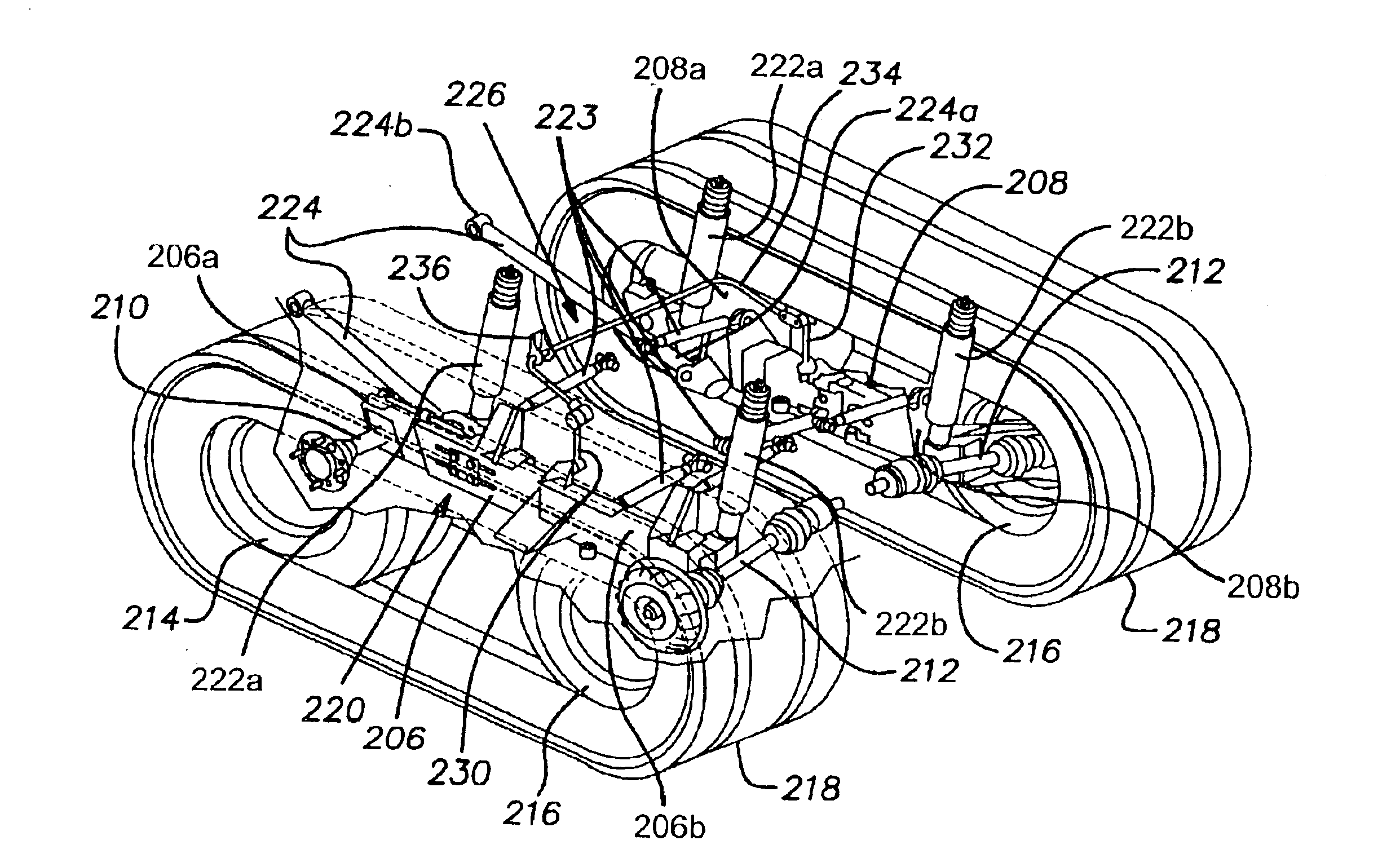
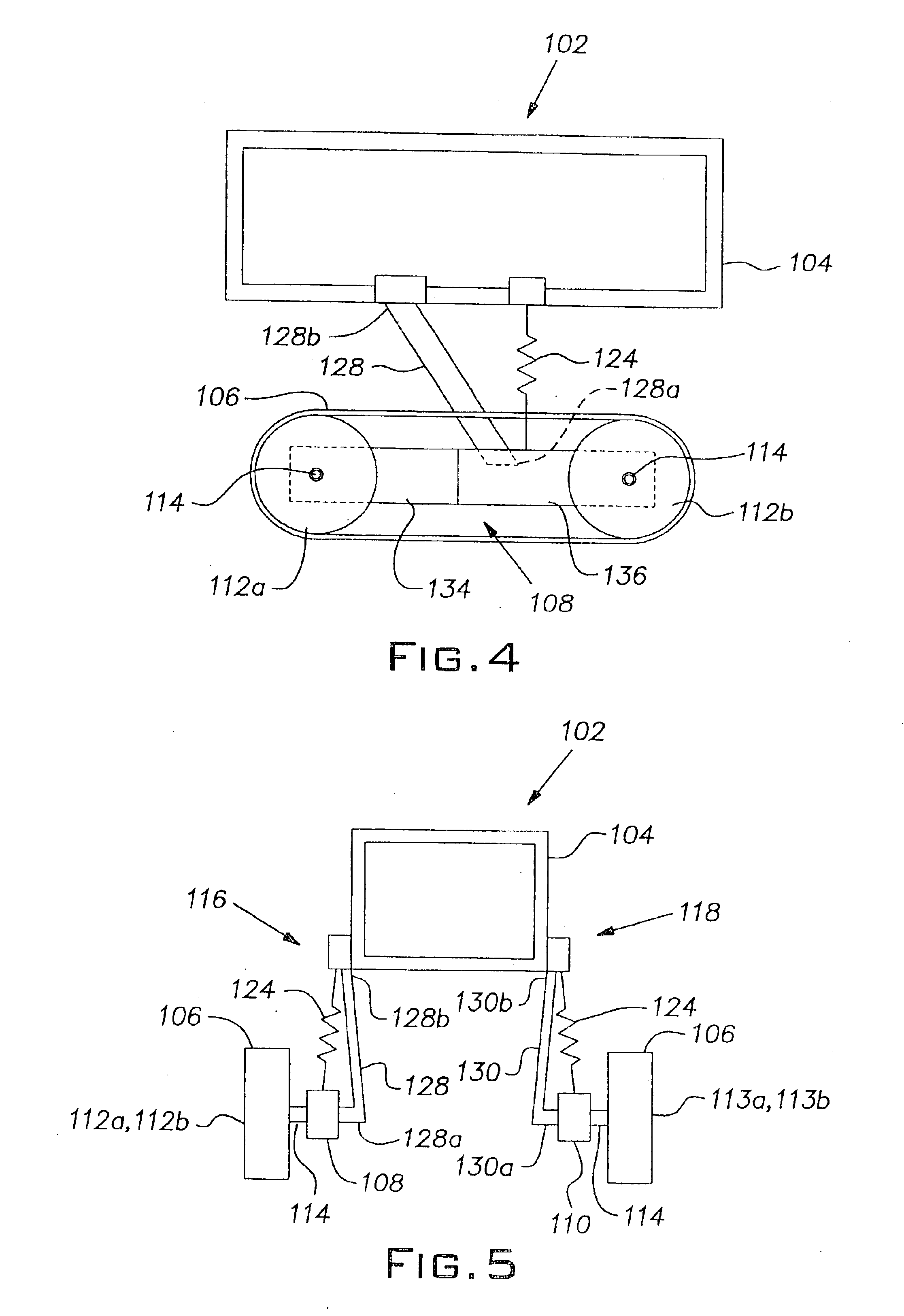
The present invention relates to a suspension system for a half-track vehicle. Initially, it is noted that the drawings are not to scale, but will be more easily understood by a person of ordinary skill in the art than drawings from another perspective or drawings shown in proper proportion. It is further noted that the drawings do not show any other structures attached to the vehicle, nor do they show any structures necessary for the functioning of the vehicle that are not directly related to the suspension structure disclosed. Accordingly, the vehicle shown in the drawing figures may not be functional without the other parts, such as a drive train and the like. However, any drive train that may be used in connection with the present structure is relatively conventional in nature. A person of ordinary skill in the art can easily adapt a known MUV or ATV drive train for use in connection with the present vehicle.

FIGS. 4 and 5 schematically illustrate a rear portion of a half-track v...


PUM


Abstract

A half-track all-terrain vehicle having an independent suspension system that provides an improved vehicle ride and facilitates traversing obstacles. The vehicle includes a frame, a pair of beams that each holds front and rear wheels, and a suspension system extending between the each beam and the frame. The suspension system includes a plurality of cushions. The cushions are tuned such that forward cushions have a relatively greater suspension stroke than the rearward cushions and thereby permit the front wheels to engage the ground sequentially before the rear wheels when the vehicle goes over a step or drop off. The suspension system is further tuned to permit the vehicle to traverse an obstacle having a height that is slightly lower than the frame clearance by permitting the front wheels to lift vertically to a distance essentially equal to the frame clearance.

Description

BACKGROUND OF THE INVENTION1. Field of the InventionThe present invention generally relates to vehicle suspension systems and, more particularly, toward an independently suspended beam structure for a multi-use vehicle.2. Description of Related ArtIt is known to independently suspend wheels from a vehicle frame. An independently suspended wheel is able to move in one or more directions without affecting the movement of any other wheels. It is desirable to independently suspend wheels to improve the ride of a vehicle when traveling over a road or ground that may be uneven. It is also desirable to use a track on each side of the vehicle. The use of a track, rather than individual wheels only, improves the vehicle's flotation on soft ground as well as the traction. It is particularly important to use an independent suspension system when a track is used, to maximize the amount of surface area of each track in contact with the ground on each side of the vehicle.It is also known to suspe...

Claims


Application Information

Patent Timeline
Patent Type & Authority Patents(United States)
IPC IPC(8): B60G5/00B62D55/104B62D55/00
CPCB60G5/00B62D55/104B62D55/00
Inventor BOWERS, LEE N.KITTEL, MARKISHII, HIDEFUMI
Owner HONDA MOTOR CO LTD
Why Eureka
Try Eureka