Web material advance system for web material applicator

a technology of web material and advance system, which is applied in the direction of paper/cardboard containers, mechanical control devices, instruments, etc., can solve the problem of uneconomical mechanism

Inactive Publication Date: 2005-05-17
ADALIS
View PDF59 Cites 81 Cited by
  • Summary
  • Abstract
  • Description
  • Claims
  • Application Information

AI Technical Summary

Benefits of technology

[0006]The present invention is directed to a dispenser for a length of tape, comprising a tape feed section for advancing the tape along a predetermined path, a tape applicator section for accepting the tape, and a substrate feed section for advancing the substrate past the applicator section. The tape feed section comprises a feed roll and associated means for advancing tape from a supply, i.e. a pressure roll or increased frictional surface or a positive drive. Further, it includes a vacuum anvil roll for picking up the tape from the feed roll and a knife roll for cutting lengths of tape on the vacuum roll. Drive means rotate the vacuum anvil roll. The vacuum roll has an outer foraminous surface to receive subatmospheric pressure near the surface of the roll and above atmospheric pressure at a desired location about the path of the roll. The vacuum anvil roll has an outer foraminous cylindrical peripheral surface and means for applying atmospheric pressure at said surface throughout a portion of the surface during each rotation thereof. Means support the vacuum roll for rotation about an axis perpendicular to the path of the web material. A cutting wheel (rotary knife roll) positioned near the vacuum roll, for rotation with the vacuum roll, engages the web material on the vacuum roll opposite a hardened insert, to cut the same to the desired length. An application means receives the cut length of web material and advances the cut length to a substrate. Changes in the length of web material can be made with this tape advancing section without mechanical changes to the basic components. The feed roll and the vacuum roll have separate drive means for affording rotation of the feed roll at a peripheral surface speed different from the peripheral speed of the surface of the vacuum roll. The speeds can be effectively adjusted by the use of a motor control and the positioning of a length of tape on the substrate is accomplished by a programmable logic controller so that the length of tape applied and the location of the tape on the substrate can be changed easily.

Problems solved by technology

The stopping and starting of the lamina and substrate render such a mechanism to be uneconomical for a hot melt feeder and carton laminator, which operate typically at 600 to 1000 feet per minute (182 meters to 305 meters per minute).

Method used


Image

  • Web material advance system for web material applicator
  • Web material advance system for web material applicator
  • Web material advance system for web material applicator

Examples


Embodiment Construction

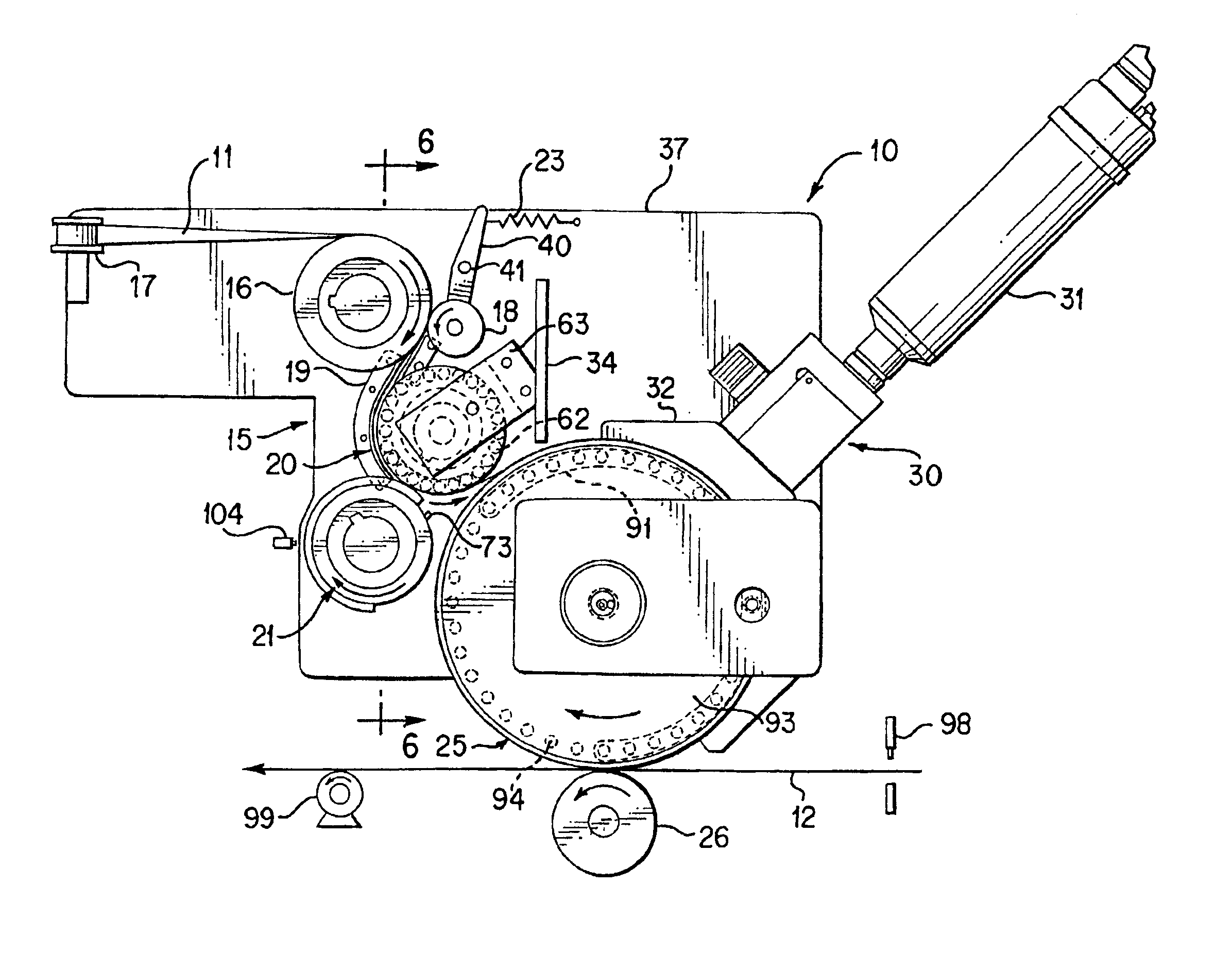
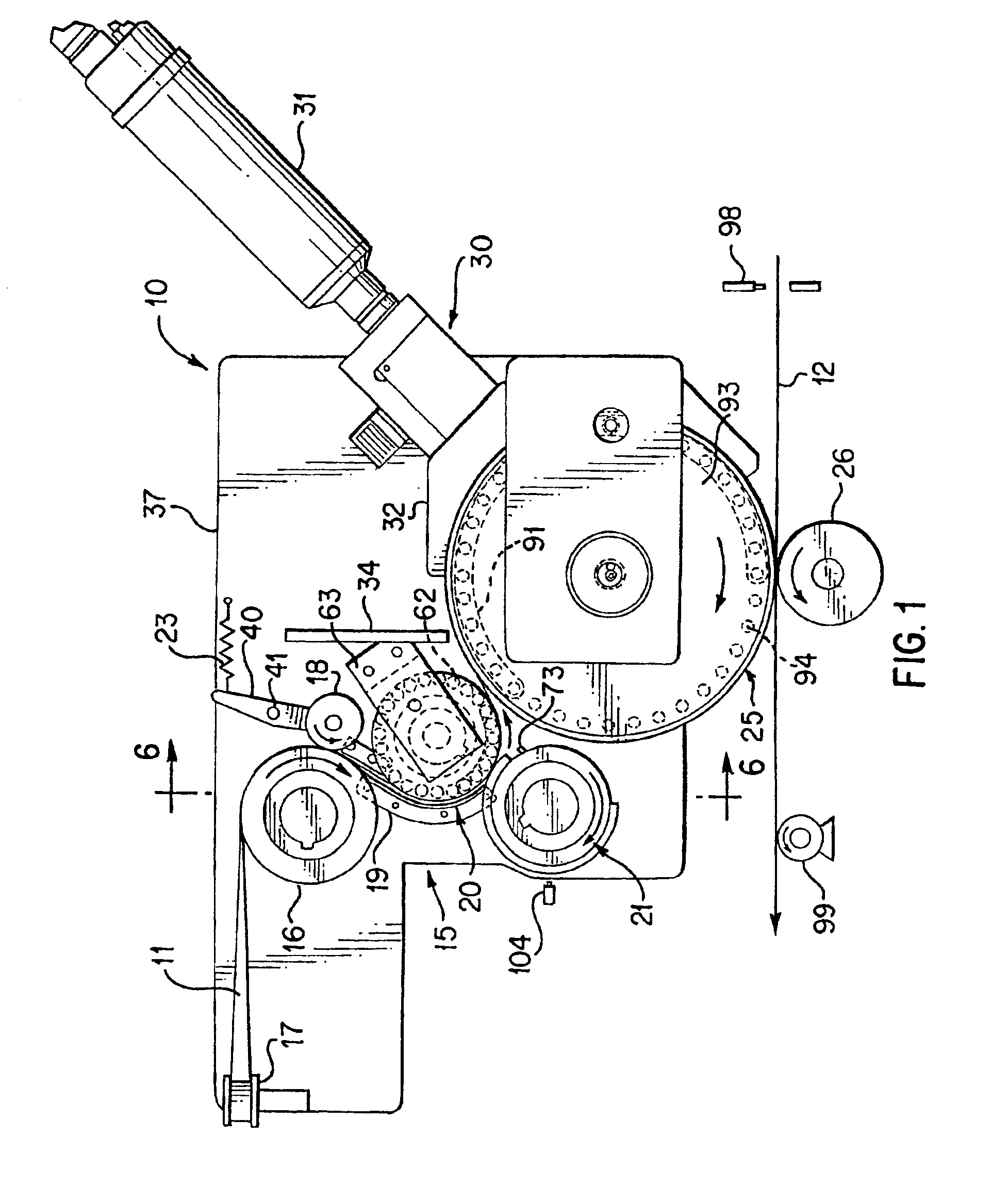
[0019]This invention relates to a machine for the handling of a tape to apply different lengths thereof to a moving substrate, and to place the cut length of tape in the desired position. In real time this means applying the tape to cartons at predetermined locations, to apply the cutting edge as described in copending application Ser. No. 09 / 154,005 filed Sep. 16, 1998, and assigned to the assignee of this application, or to a web of carton material for reinforcing the carton material or to form a reinforced handle. The application speed can be approximately 1000 feet per minute. An example of cutting edge tape is a film tape coated with adhesive for application to the carton board of a carton for a convolutely wound roll of sheet material in which the tape serves as the cutting edge on the carton for the material. The tape is formed of a polymeric film material in a continuous strip, which is stiff enough, when applied to the free edge of a carton to provide the cutting function. ...


PUM

PropertyMeasurementUnit
thicknessaaaaaaaaaa
diameteraaaaaaaaaa
lengthaaaaaaaaaa

Abstract

An apparatus for applying a cutting edge tape or a reinforcing tape to a substrate by feeding and cutting lengths of tape and advancing the lengths to a vacuum wheel applicator, the feed section of the apparatus comprising a feed roll, an anvil vacuum roll, and a rotary knife adjacent to the anvil vacuum roll, and means for adjusting the speed of the feed roll and the speed of the anvil vacuum roll to vary the length of the tape advanced to the applicator.

Description

RELATED APPLICATION[0001]This application is a Continuation-in-Part of application Ser. No. 09 / 703,968, filed Nov. 1, 2000, now abandoned.FIELD OF THE INVENTION[0002]The present invention relates to an improved web material dispenser for advancing a web material to an applicator, such as a tape applicator for applying a strip of tape to form a cutting edge, a reinforcing tape, a box sealer, and the like. The system utilizes a feed roller to advance the web to a vacuum anvil roll where the web material is cut and advanced to a vacuum wheel applicator. In one aspect to a web material delivery system capable of changing the length of the web material delivered to the applicator. The speed of the feed roll and the speed of the independently driven vacuum anvil roll and cutting roller are determined by a motor control and the position of the web material on the substrate is regulated by a programmable logic control and encoder set by an indicator triggered by the substrate.BACKGROUND OF ...

Claims


Application Information

Patent Timeline
Patent Type & Authority Patents(United States)
IPC IPC(8): B26D1/01B31B1/90B31B1/74B26D1/40B26D5/20B26D7/01B65H35/00
CPCB26D1/405B26D7/018B31B1/90B65H35/0013B65H35/0066B26D5/20Y10T156/1339B31B2201/9004B65H2406/30Y10T156/1077Y10T156/12Y10T156/1712Y10T156/125Y10T156/133Y10T156/1075Y10T156/1095Y10T156/1097Y10T156/1062Y10T156/1322B31B50/811Y10T83/8733Y10T156/1085
Inventor MIDDELSTADT, SCOTT K.HARTMAN, JAMES N.
Owner ADALIS
Why Eureka
Try Eureka