Timer of electric timepiece
- Summary
- Abstract
- Description
- Claims
- Application Information
AI Technical Summary
Problems solved by technology
Method used
Image
Examples
first embodiment
[0021][First Embodiment]
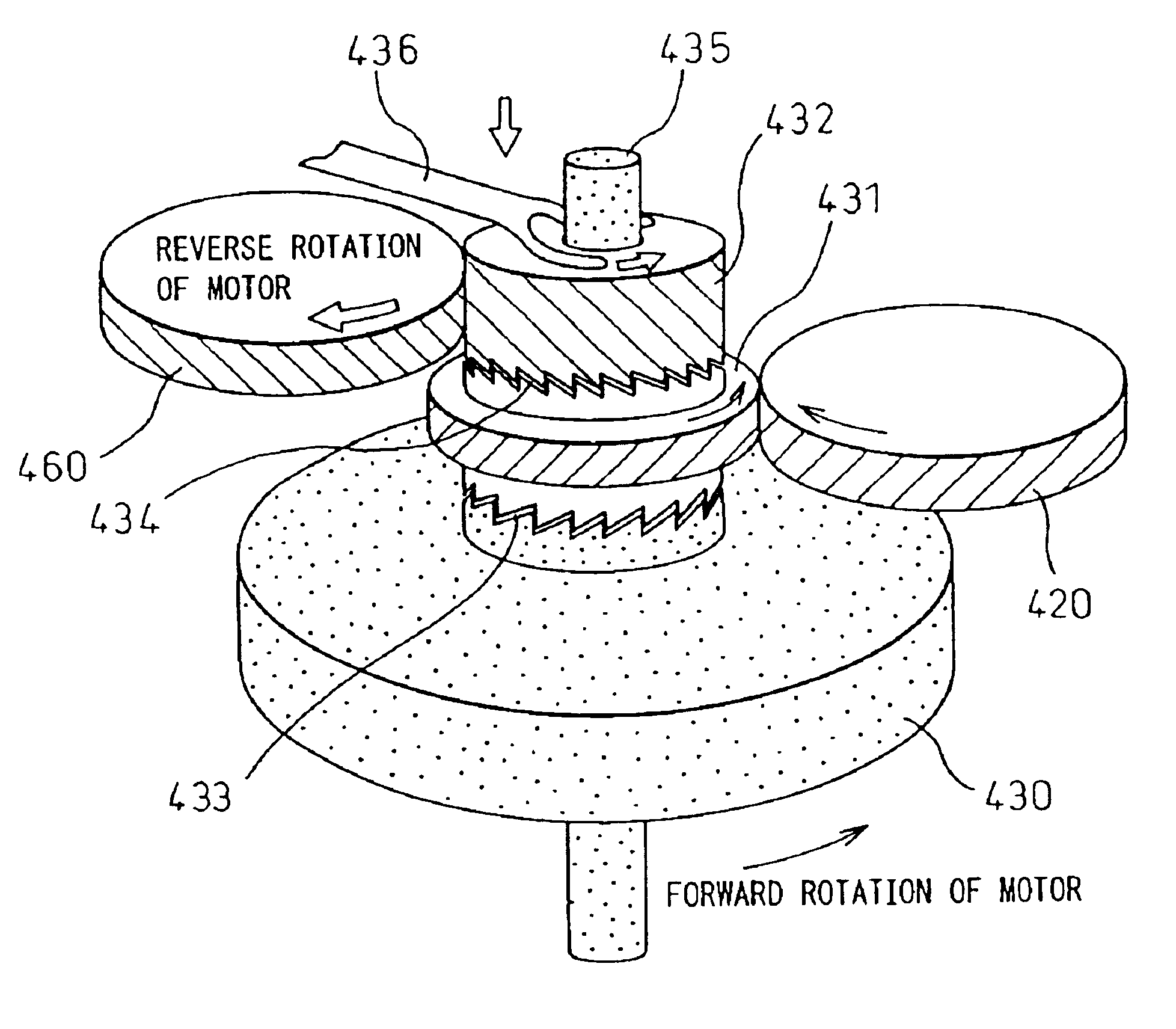
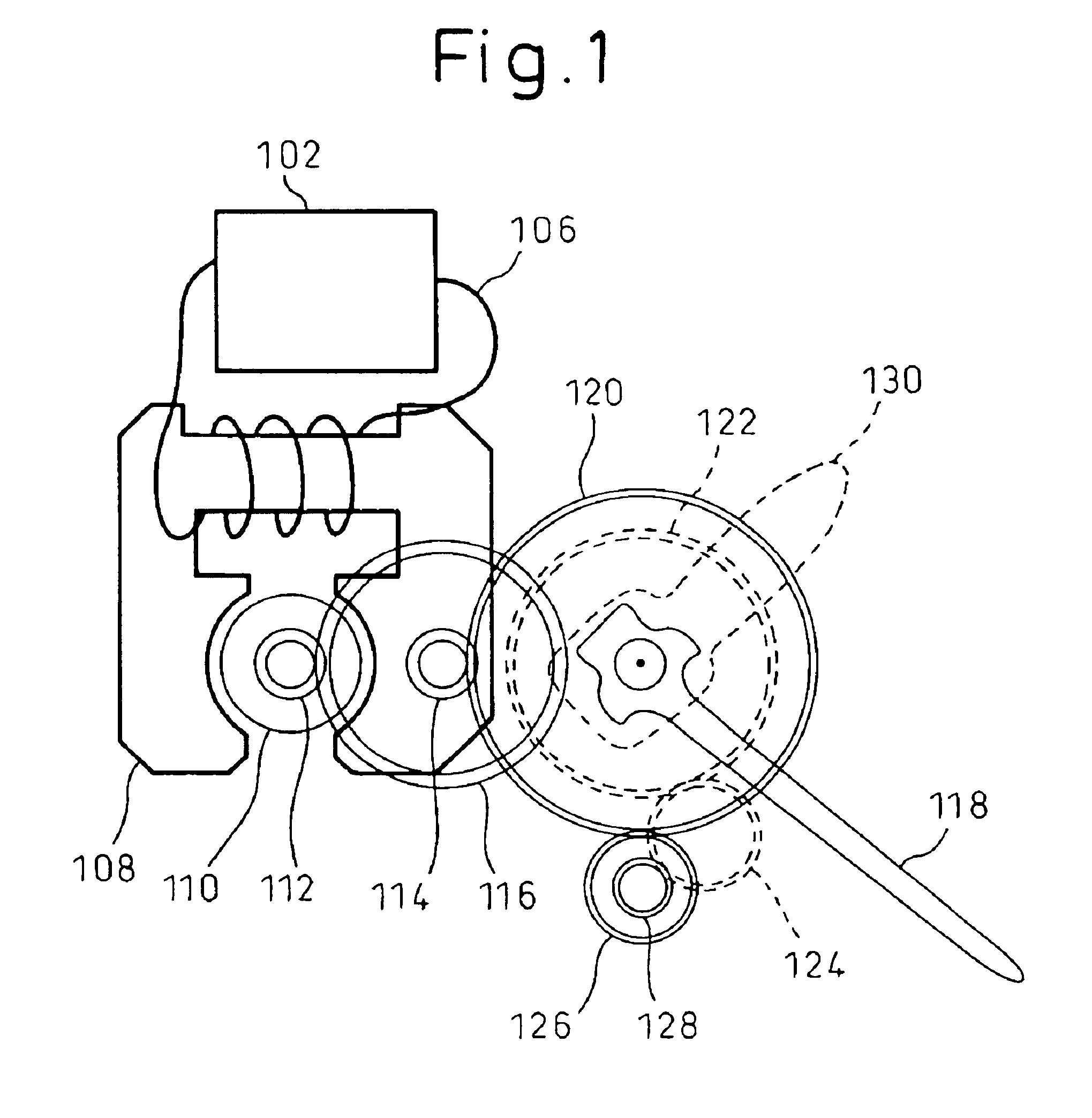
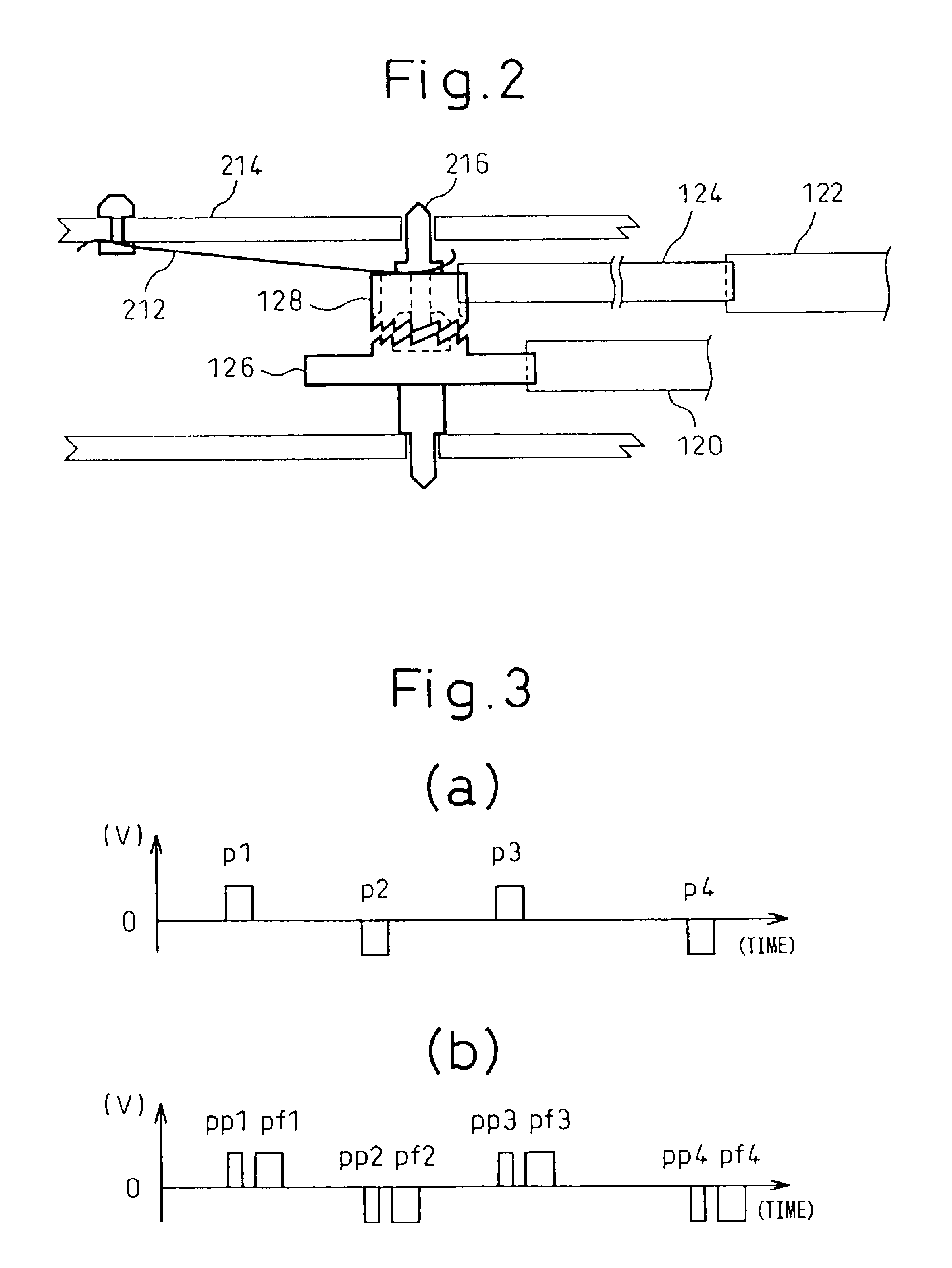
[0022]FIG. 1 shows an outline of a plurality of wheel trains having a branch mechanism according to the present invention. In FIG. 1, 102 denotes a driving circuit mechanism of a motor as an electromagnetic converter. 106 denotes a driving coil of the motor. 108 denotes a yoke of the motor. 110 denotes a rotor that rotates, and that is made of a strong magnet. 112 denotes a pinion that is formed coaxially with a rotor shaft. 116 denotes a gear that is engaged with the pinion 112. 114 denotes a pinion that is fixed coaxially with the gear 116. 120 denotes a second hand gear that is engaged with the pinion 114, and that is fixed to the shaft of a minute hand 118. When the rotor 110 rotates 180 degrees every one second, the second hand gear 120 rotates in the same direction by six degrees. 126 denotes a gear that is engaged with the second hand gear 120, and that is coupled with a coaxial gear 128 via a sliding engagement mechanism (refer to FIG. 2). In the norm...
second embodiment
[0059][Second Embodiment]
[0060]FIG. 7 is a block diagram that shows transmission routes of timepiece wheel trains according to the present invention, and shows the outline of a branch mechanism and a merge mechanism according to the present invention. The structure shown in FIG. 7 has a characteristic that the branch mechanism and the merge mechanism of wheel trains are provided in the transmission routes of second, minute, hour, and day of the mechanical wheel trains of a timepiece. In the present invention, the wheel trains have two transmission routes having different reduction gear ratios. By occasionally switching between the routes, it is possible to control the operation of the wheel trains for holding time according to a plurality of methods. For example, the “normal driving mode” of driving the second hand, the minute hand, and the hour hand, and the “power saving driving mode” of driving only the minute hand and the hour hand are provided. In order to switch between the no...
third embodiment
[0084][Third Embodiment]
[0085]An embodiment of a synchronization mechanism according to the present invention will be explained next. The synchronization mechanism explained below can be used to synchronize the electric time keeping time of the electric time keeping device ETK with the mechanical time keeping time of the mechanical time keeping device MMK in the first embodiment and the second embodiment explained above.
[0086]In order to synchronize the electric time keeping time of the electric time keeping device ETK with the mechanical time keeping time of the mechanical time keeping device MMK, various kinds of methods may be employed. One of the methods with the least manufacturing load is to stop the timepiece by pulling the crown by one stage when the second hand comes to a correct minute position (=0second), reset both the electric time keeping device ETK and the electric mechanical time holding time keeping device MTK to 0, and the Tet and the Tmt are synchronized at the se...
PUM
 Abstract
Description
Claims
Application Information
 - R&D
- Intellectual Property
- Life Sciences
- Materials
- Tech Scout
- Unparalleled Data Quality
- Higher Quality Content
- 60% Fewer Hallucinations
Browse by: Latest US Patents, China's latest patents, Technical Efficacy Thesaurus, Application Domain, Technology Topic, Popular Technical Reports.
© 2025 PatSnap. All rights reserved.Legal|Privacy policy|Modern Slavery Act Transparency Statement|Sitemap|About US| Contact US: help@patsnap.com


