
Communication system

a communication system and communication system technology, applied in the field of communication systems, can solve the problems of increasing the number of mutual interference, increasing the cost, increasing the number, etc., and achieve the effects of large signal processing scale, large size, and increasing mutual interferen

Inactive Publication Date: 2005-05-17
HITACHI LTD +2
View PDF8 Cites 5 Cited by
  • Summary
  • Abstract
  • Description
  • Claims
  • Application Information

AI Technical Summary

Benefits of technology

[0009]In a mobile communication system utilizing code division multiple access as described above, an increase in mutual interference inevitably occurs as a result of an increase in the number of users who simultaneously communicate. Therefore, interference cancellation techniques are indispensable techniques. Among such interference cancellation techniques, multi-user reception type interference cancellation techniques require a signal processing unit for performing a process of suppressing interference components including a plurality of correlators and re-spreaders because they utilize information of a plurality of user signals to be demodulated. The signal processing unit for performing a process of suppressing interference components has a large size and involves a large scale of signal processing because it has a multi-stage configuration for improving the effect of canceling interference components. As a result, a communication system utilizing such an interference cancellation method needs an apparatus of a large scale is required at a base station, thereby increasing cost.
[0010]It is an object of the invention to provide a communication system utilizing code division multiple access in which any increase in the scale of an apparatus at a base transceiver station in simultaneous communication with a plurality of radio mobile station apparatuses is prevented by providing an interference suppressing function for suppressing mutual interference attributable to an increase in the number of users of the communication.
[0011]It is another object of the invention to provide a low-cost communication system utilizing code division multiple access which enables prevention of any reduction of channel utilization communication with high quality.
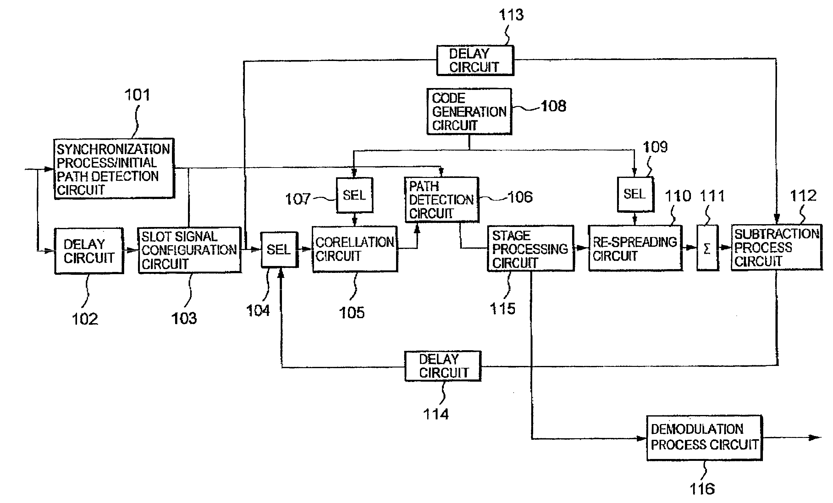
[0012]In order to achieve the above objects according to the present invention, there is provided a base transceiver station for use in communication with a plurality of radio mobile station apparatuses based on code division multiple access. The base transceiver station comprises a reception signal interference canceller device. Further, the interference canceller device comprises: a slot configuration circuit for dividing a reception signal at certain time intervals, converting the divided signal into signals at a faster cycle and converting into a signal having a serial slot configuration as many the converted signals as stages for stage processing on a signal identical to the converted signals at a faster cycle; a correlation circuit for performing a despreading process on the signal having the slot configuration; a stage addition circuit for adding the number of stages for stage processing to the despread signals; a re-spreading circuit for performing a re-spreading process on the signals which have been subjected to the stage addition; a synthesis circuit for performing a process of synthesizing all of the spread signals which have been subjected to the re-spreading process to generate replica signals; and a subtraction process circuit for performing a subtraction process between the replica signals and the reception signals. By the base transceiver station, signals obtained by subtraction process for the replica signals and the reception signals are repeatedly fed back to the correlation circuit thereby to eliminate an interference component.

Problems solved by technology

In a mobile communication system utilizing code division multiple access as described above, an increase in mutual interference inevitably occurs as a result of an increase in the number of users who simultaneously communicate.
As a result, a communication system utilizing such an interference cancellation method needs an apparatus of a large scale is required at a base station, thereby increasing cost.

Method used


Image

  • Communication system
  • Communication system
  • Communication system

Examples


Embodiment Construction

[0026]An embodiment of a communication system according to the invention will now be described in detail with reference to the drawings.

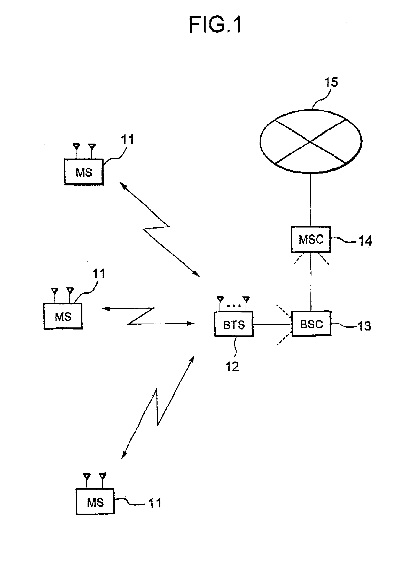
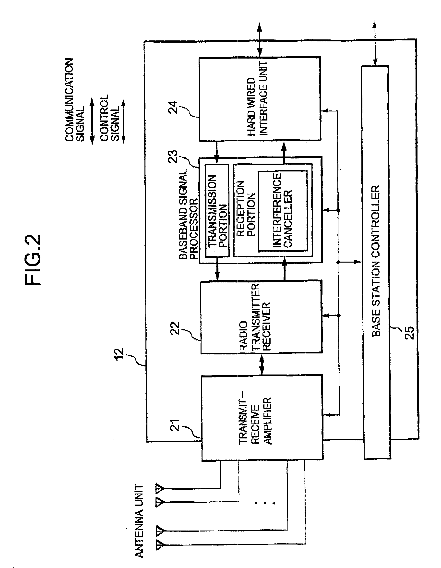
[0027]FIG. 1 is a block diagram showing a configuration of a communication system utilizing code division multiple access according to an embodiment of the invention. FIG. 2 is a block diagram showing a configuration of a base transceiver station apparatus having an interference-canceling device. First, a schematic description will be made on configurations of the communication system and base transceiver station of the present embodiment. In FIGS. 1 and 2, 11 represents a mobile station (MS); 12 represents a base transceiver station (BTS); 13 represents a base station controller (BSC); 14 represents a mobile switching center(MSC): 15 represents a public switched telephone network; 20 represents an antenna unit; 21 represents a transmit-receive amplifier; 22 represents a radio transmitter receiver; 23 represents a baseband processor; 24 represents a...


PUM


Abstract

A low-cost communication system utilizing a code division multiple access, which controls scale-up of an apparatus due to the provision of an interference suppressing function in a base transceiver station, prevents the reduction of channel utilization efficiency, and enables a high-quality communication. Conventionally, a signal obtained through an interference cancellation stage process has been processed at subsequent cascade-connected stages. The interference cancellation stage process has been carried out by cascade-connecting several circuits performing the same process in a multi-stage interference-canceling device. However, in the present invention, by performing a demodulation process for generating replica signals, feeding back the replica signals to a correlation circuit for another demodulation process, and repeating the same signal process, the interference cancellation stage process is carried out. Such a configuration enables reduction of hardware.

Description

[0001]This application claims a priority based on Japanese Patent Application No. 2000-20657 filed on Jan. 28, 2000, the entire contents of which are incorporated herein by reference for all purposes.BACKGROUND OF THE INVENTION[0002]Field of the Invention[0003]The present invention relates to a communication system and, more particularly, to a radio communication system based on the code division multiple access system.[0004]A radio communication system employing the code division multiple access method has characteristics suitable for mobile communication, i.e., its strength against mutual interference with other systems, its adaptability to a multipath, capability of easy hand-off, excellent secrecy and so on. However, a communication system based on the code division multiple access method is different from other multiple access methods in that a plurality of terminal users existing within the same base station cell simultaneously communicate using the same frequency and the same...

Claims


Application Information

Patent Timeline
Patent Type & Authority Patents(United States)
IPC IPC(8): H04B1/707H04J13/00H04B1/7093H04B1/7107H04W76/02H04W88/08
CPCH04B1/7107
Inventor SAITO, JOICHISHIMIZU, HIDEKITSUBAKI, NAOKIISHIDA, YUUJISUZUKI, TOSHINORI
Owner HITACHI LTD
Learn More