Ultrathin optical panel and a method of making an ultrathin optical panel

a technology which is applied in the field of ultrathin display panel and ultrathin film display panel, can solve the problems of inability to actually blacken direct view images, cumbersome screens, and practical limits of conventional cathode ray tubes, so as to minimize depth and improve contrast

Inactive Publication Date: 2005-05-17
BROOKHAVEN SCI ASSOCS
View PDF45 Cites 9 Cited by
  • Summary
  • Abstract
  • Description
  • Claims
  • Application Information

AI Technical Summary

Benefits of technology

[0010]The present invention is directed to an ultrathin optical panel. The panel includes a plurality of stacked optical waveguides, wherein the plurality forms an outlet face and an inlet face, and at least one coupler connected to the inlet face which redirects light along a non-perpendicular axis to the inlet face to a perpendicular axis to the inlet face. The coupler allows the panel to be created using simple light generating equipment, and allows that equipment to be mounted in close proximity with the inlet face.
[0012]The present invention solves problems experienced in the prior art, such as the required use of expensive and cumbersome projection equipment, by providing a light inlet which, though smaller in surface area than the outlet face, is large enough and symmetrical enough to not necessitate the use of expensive projection equipment. The present invention also retains the advantages which correspond to a stacked waveguides panel, such as improved contrast and minimized depth.

Problems solved by technology

Conventional cathode ray tubes have a practical limit in size, and are relatively deep to accommodate the required electron gun.
However, such screens have various viewing shortcomings including limited viewing angle, resolution, brightness, and contrast, and such screens are typically relatively cumbersome in weight and shape.
However, it is impossible for direct view CRTs to actually be black because they utilize phosphors to form images, and those phosphors are non-black.
Such a panel may be thin in its depth compared to its height and width, and the cladding of the waveguides may be made black to increase the black surface area, but such a panel may require expensive and cumbersome projection equipment to distribute the image light across the narrow inlet face, which equipment thereby increases the total size of the panel.

Method used


Image

  • Ultrathin optical panel and a method of making an ultrathin optical panel
  • Ultrathin optical panel and a method of making an ultrathin optical panel
  • Ultrathin optical panel and a method of making an ultrathin optical panel

Examples


Embodiment Construction

[0018]It is to be understood that the figures and descriptions of the present invention have been simplified to illustrate elements that are relevant for a clear understanding of the present invention, while eliminating, for purposes of clarity, many other elements found in a typical optical display panel. Those of ordinary skill in the art will recognize that other elements are desirable and / or required in order to implement the present invention. However, because such elements are well known in the art, and because they do not facilitate a better understanding of the present invention, a discussion of such elements is not provided herein.

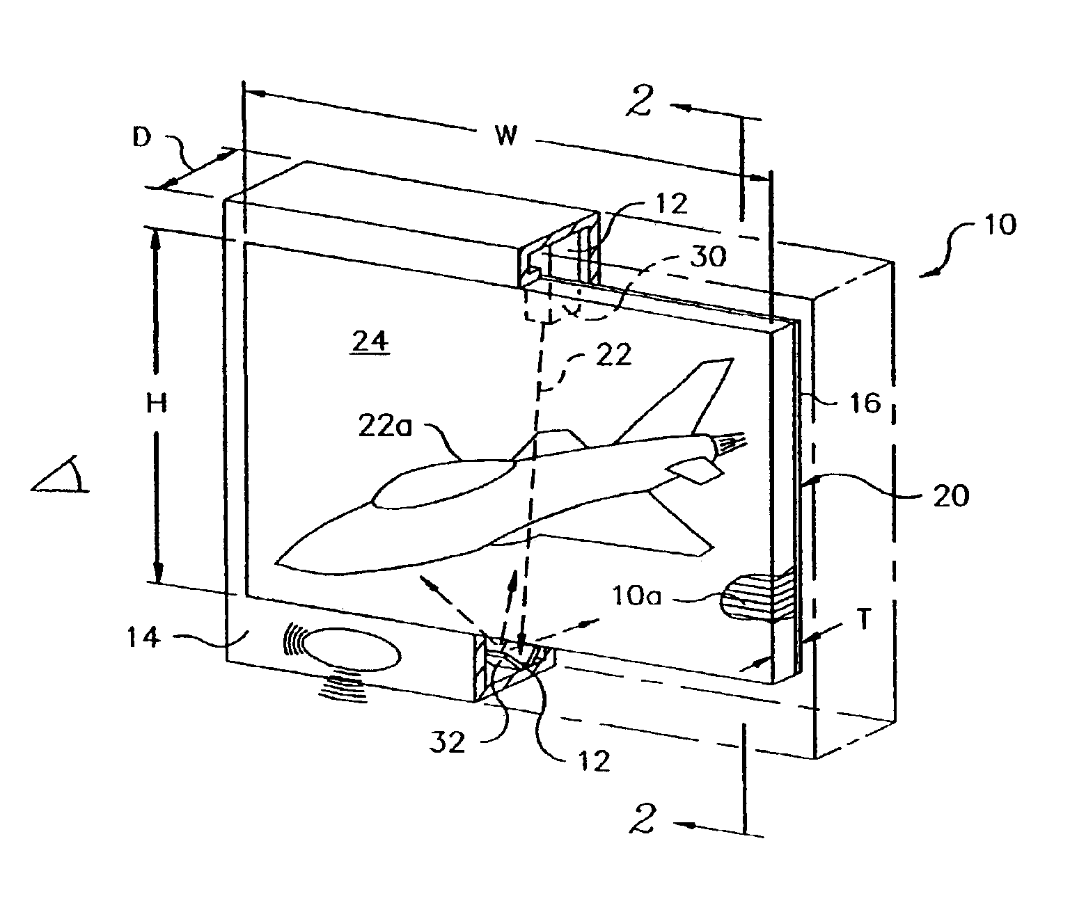
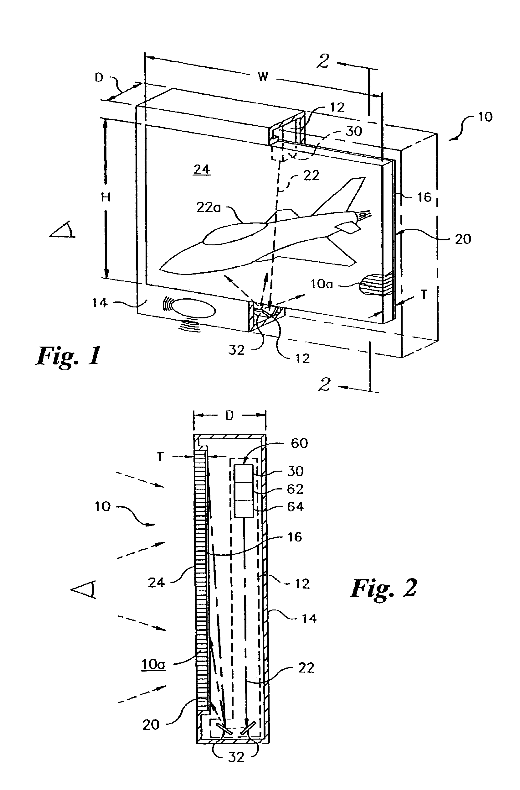
[0019]FIG. 1 is an isometric view schematic illustrating an optical panel 10. The optical panel 10 includes a plurality of waveguides 10a, wherein one end of each waveguides 10a forms an inlet for that waveguides, and wherein the opposite end of each waveguides 10a forms an outlet for that waveguides 10a, a light generation system 12, a housing 14...


PUM


Abstract

An ultrathin optical panel, and a method of producing an ultrathin optical panel, are disclosed, including stacking a plurality of glass sheets, which sheets may be coated with a transparent cladding substance or may be uncoated, fastening together the plurality of stacked coated glass sheets using an epoxy or ultraviolet adhesive, applying uniform pressure to the stack, curing the stack, sawing the stack to form an inlet face on a side of the stack and an outlet face on an opposed side of the stack, bonding a coupler to the inlet face of the stack, and fastening the stack, having the coupler bonded thereto, within a rectangular housing having an open front which is aligned with the outlet face, the rectangular housing having therein a light generator which is optically aligned with the coupler. The light generator is preferably placed parallel to and proximate with the inlet face, thereby allowing for a reduction in the depth of the housing.

Description

CROSS REFERENCE TO RELATED APPLICATIONS[0001]This application is a continuation of U.S. patent application Ser. No. 09 / 845,085, filed Apr. 27, 2001, now U.S. Pat. No. 6,519,400, which is a continuation of U.S. patent application Ser. No. 09 / 318,934, filed May 26, 1999, now U.S. Pat. No. 6,301,417, which is a continuation-in-part of U.S. patent application Ser. No. 09 / 145,411, filed Aug. 31, 1998, now abandoned.STATEMENT REGARDING FEDERALLY SPONSORED RESEARCH OR DEVELOPMENT[0002]This invention was made with federal government support under contract number DE-AC02-98CH10886, awarded by the U.S. Department of Energy. The government has certain rights in the invention.BACKGROUND OF THE INVENTION[0003]1. Field of the Invention[0004]The present invention relates to planar optical displays, and, more particularly, to an ultrathin display panel and a method of making an ultrathin display panel.[0005]2. Description of the Background[0006]Optical screens typically use cathode ray tubes (CRTs)...

Claims


Application Information

Patent Timeline
Patent Type & Authority Patents(United States)
IPC IPC(8): G02B6/06G02B6/08H04N5/74H04N9/31G02B27/18G03B21/00
CPCG02B6/08H04N9/3129H04N9/3141H04N9/3102G02B6/06H04N5/7416Y10S385/901G02B6/04
Inventor BISCARDI, CYRUSBREWSTER, CALVINDESANTO, LEONARDVELIGDAN, JAMES T.
Owner BROOKHAVEN SCI ASSOCS
Why Eureka
Try Eureka