Mobile communications system and operation method thereof
a mobile terminal and communication system technology, applied in the field of mobile communications system and an operation method thereof, can solve the problems of liable to fraudulent use by the third party, fraudulent use of the terminal b>101/b>, etc., and achieve the effect of preventing fraudulent use of the mobile terminal
- Summary
- Abstract
- Description
- Claims
- Application Information
AI Technical Summary
Benefits of technology
Problems solved by technology
Method used
Image
Examples
first embodiment
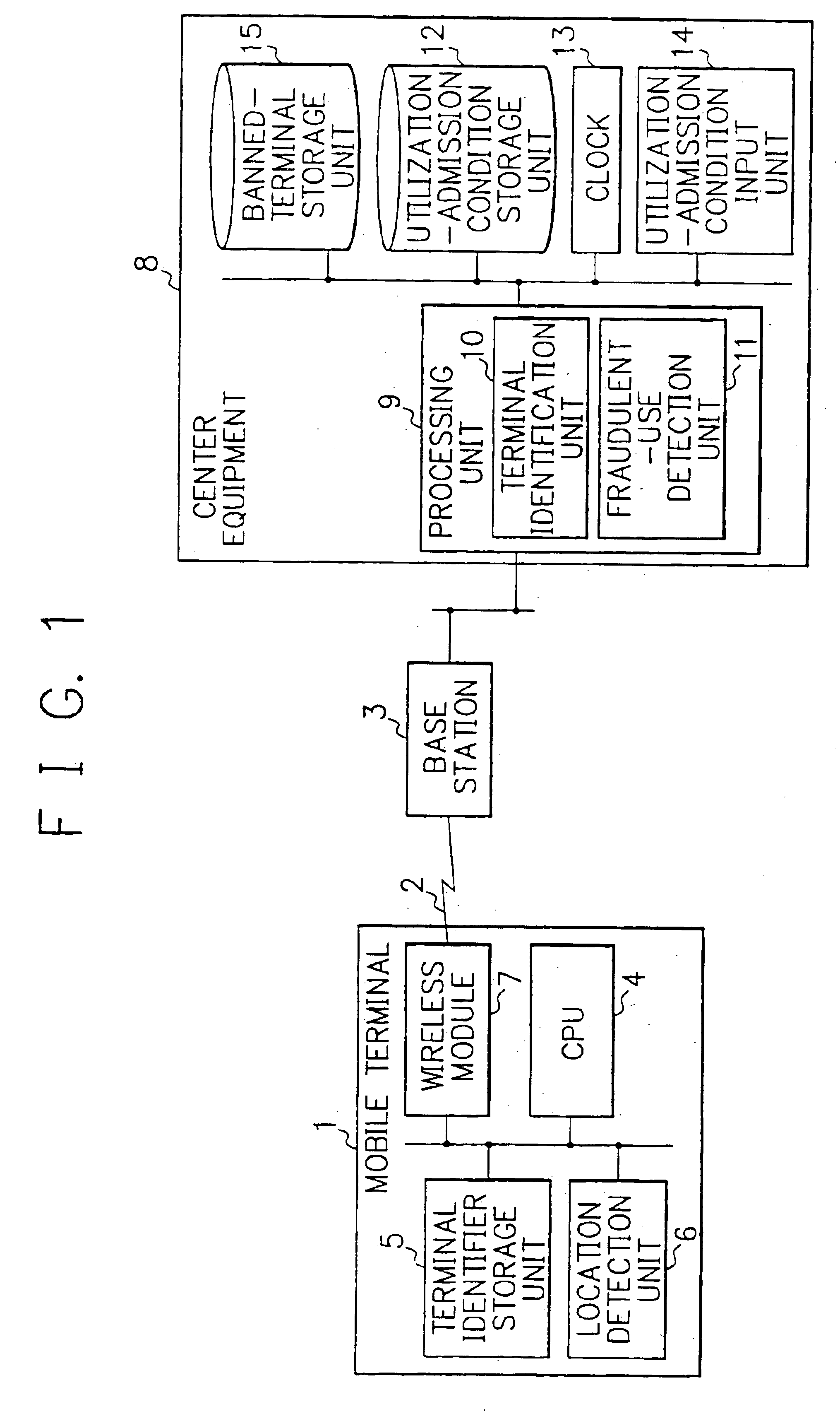
[0037]FIG. 1 is a block diagram of a mobile communication system according to a first embodiment of the present invention. The mobile communication system has both a mobile terminal 1 and a base station 3, where the mobile terminal 1 is connected to the base station 3 via a wireless communication network 2 as shown in FIG. 1.
[0038]The mobile terminal 1 includes a central processing unit (hereinafter abbreviated as a CPU). The CPU 4 is connected to a terminal-identifier storage unit 5 that stores terminal identifiers. The storage unit 5 holds identifiers which are peculiar to individual terminals.
[0039]The CPU 4 is also connected to a location detection unit 6 that detects the location of the mobile terminal 1. Preferably, the location detection unit 6 consists of a GPS (Global Positioning System) antenna. Wireless module 7 to which the CPU 4 is connected is linked to the base station 3 via the wireless communication network 2. The base station 3 is connected to a center equipment 8 ...
second embodiment
[0056]A mobile communication system according to a second embodiment of the present invention has the same structure as that of the first embodiment as described above, excluding the following points. Unlike the mobile terminal 1 of the mobile communication system according to the first embodiment, a mobile terminal 16 of the mobile communication system according to a second embodiment lacks, as shown in FIG. 3, a location detection unit. The mobile communication system according to the second embodiment, however, includes a plurality of base stations 3A, 3B, and 3C. As for other elements constituting the mobile communication system, the system according to the second embodiment is the same in structure as that according to the first embodiment.
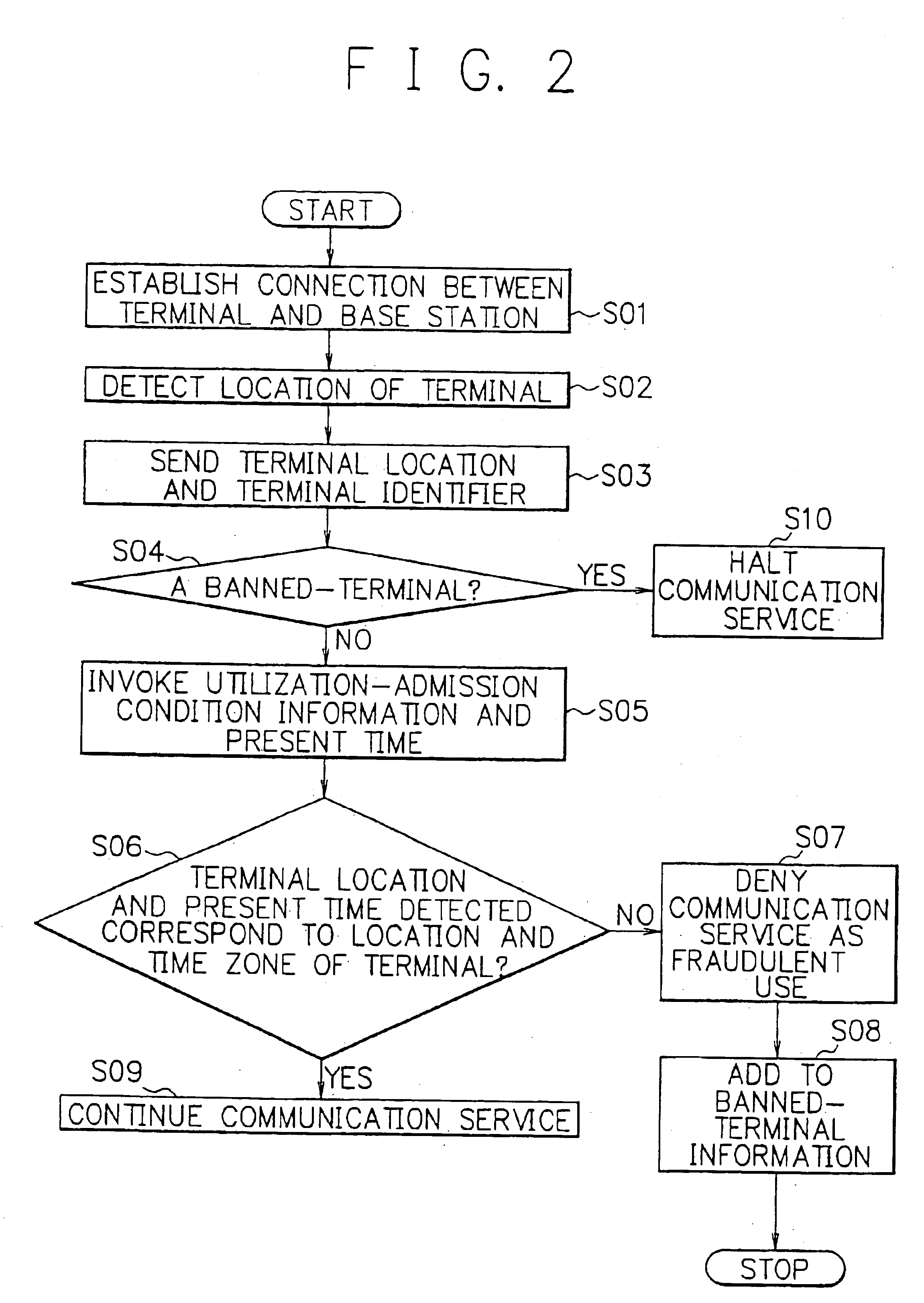
[0057]Similar to the mobile communication system according to the first embodiment, before a mobile terminal 16 is used, a utilization-admission condition information is input from a utilization-admission condition input unit 14. This informa...
third embodiment
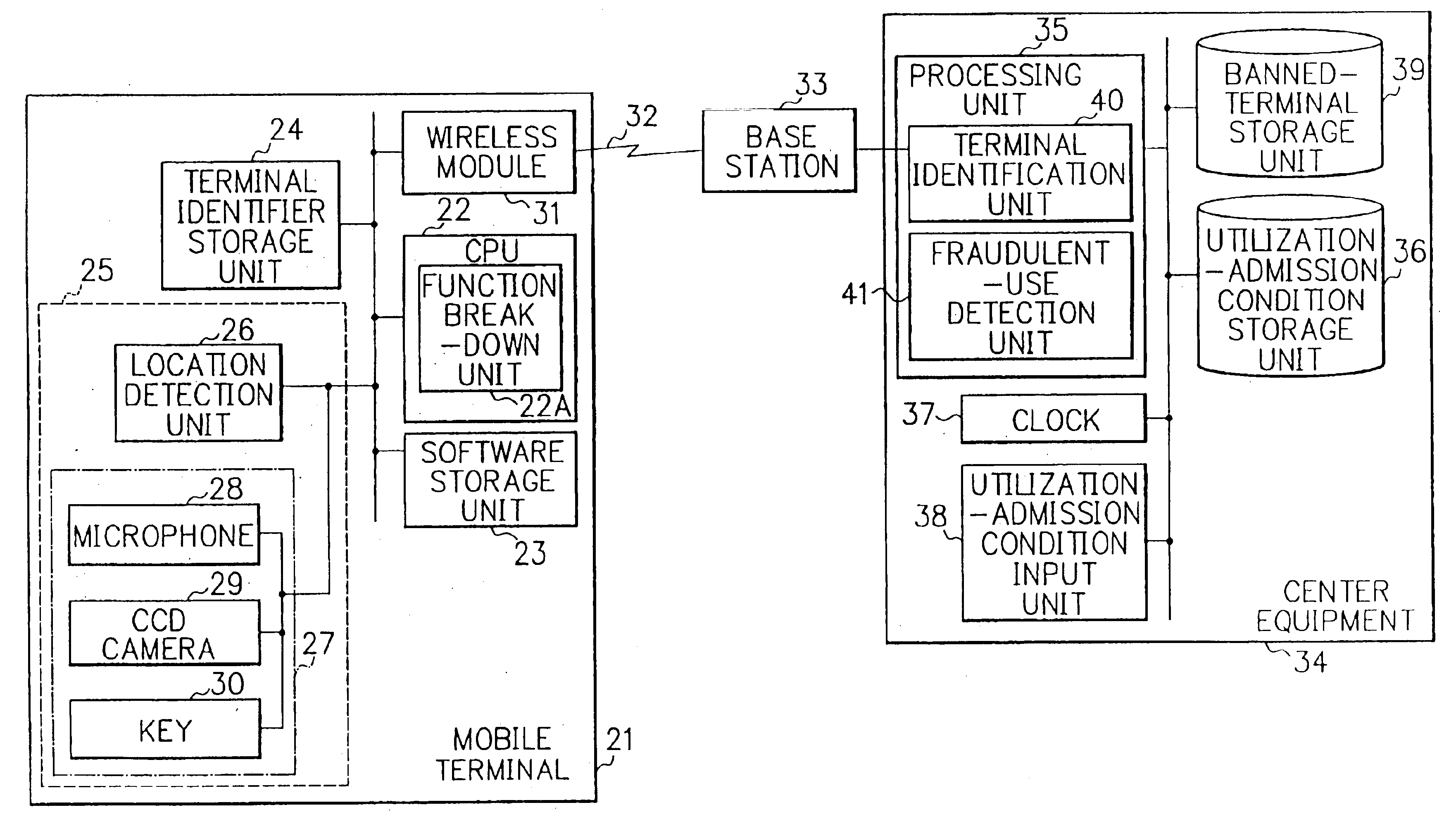
[0071]A mobile communication system according to a third embodiment of the present invention provides a mobile terminal 21 as shown in FIG. 5 that includes a central processing unit (CPU) 22. The CPU 22 is connected to a software storage unit 23 that stores programs the CPU 22 executes. The CPU 22 gives instructions to each part of the mobile terminal 21 according to the programs stored in the software storage unit 23.
[0072]The CPU 22 is also connected to a terminal-identifier storage unit 24 that stores a terminal identifier inherent to the mobile terminal 21. The CPU 22 is connected to a utilization-condition detection unit 25 for detecting a condition how the terminal 21 is being used. Utilization condition of the terminal 21 contains a geographical location where the terminal 21 exists and its user attribute.
[0073]The utilization-condition detection unit 25 includes a location detection unit 26 and a user-attribute input unit 27, each of which is connected to the CPU 22. The loc...
PUM
 Abstract
Description
Claims
Application Information
 - R&D
- Intellectual Property
- Life Sciences
- Materials
- Tech Scout
- Unparalleled Data Quality
- Higher Quality Content
- 60% Fewer Hallucinations
Browse by: Latest US Patents, China's latest patents, Technical Efficacy Thesaurus, Application Domain, Technology Topic, Popular Technical Reports.
© 2025 PatSnap. All rights reserved.Legal|Privacy policy|Modern Slavery Act Transparency Statement|Sitemap|About US| Contact US: help@patsnap.com


