Liquid flow regulator

Inactive Publication Date: 2005-05-24
AKER SOLUTIONS LTD
View PDF14 Cites 41 Cited by
  • Summary
  • Abstract
  • Description
  • Claims
  • Application Information

AI Technical Summary

Problems solved by technology

As will be explained more particularly later, a difficulty in the design of flow regulators which need to provide continuous flow at very low rates (particularly for chemical injection sub-sea) is conflict between a need for a small control orifice and avoidance of clogging by particles, as well as the provision of a substantial ‘turn-down ratio’ i.e. the ratio of the maximum to the minimum flow rate.

Method used


Image

  • Liquid flow regulator
  • Liquid flow regulator

Examples


Embodiment Construction

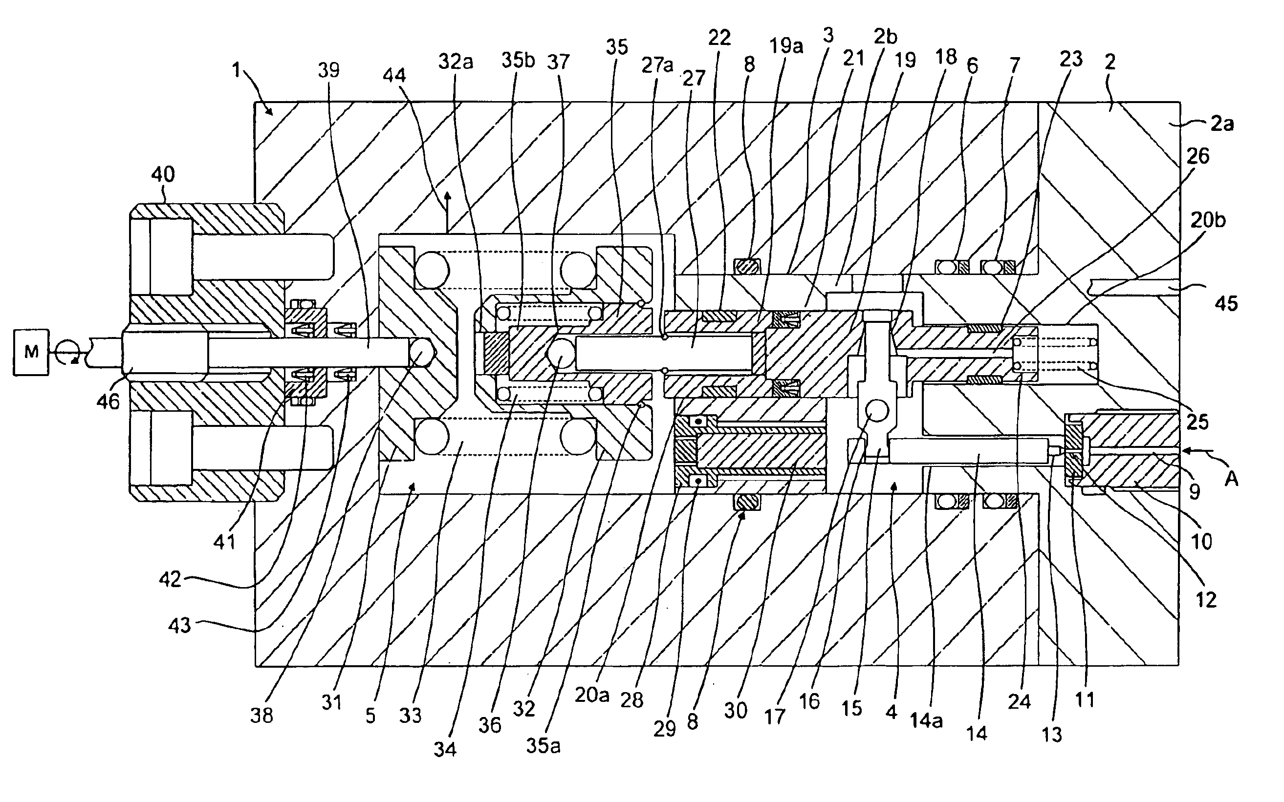
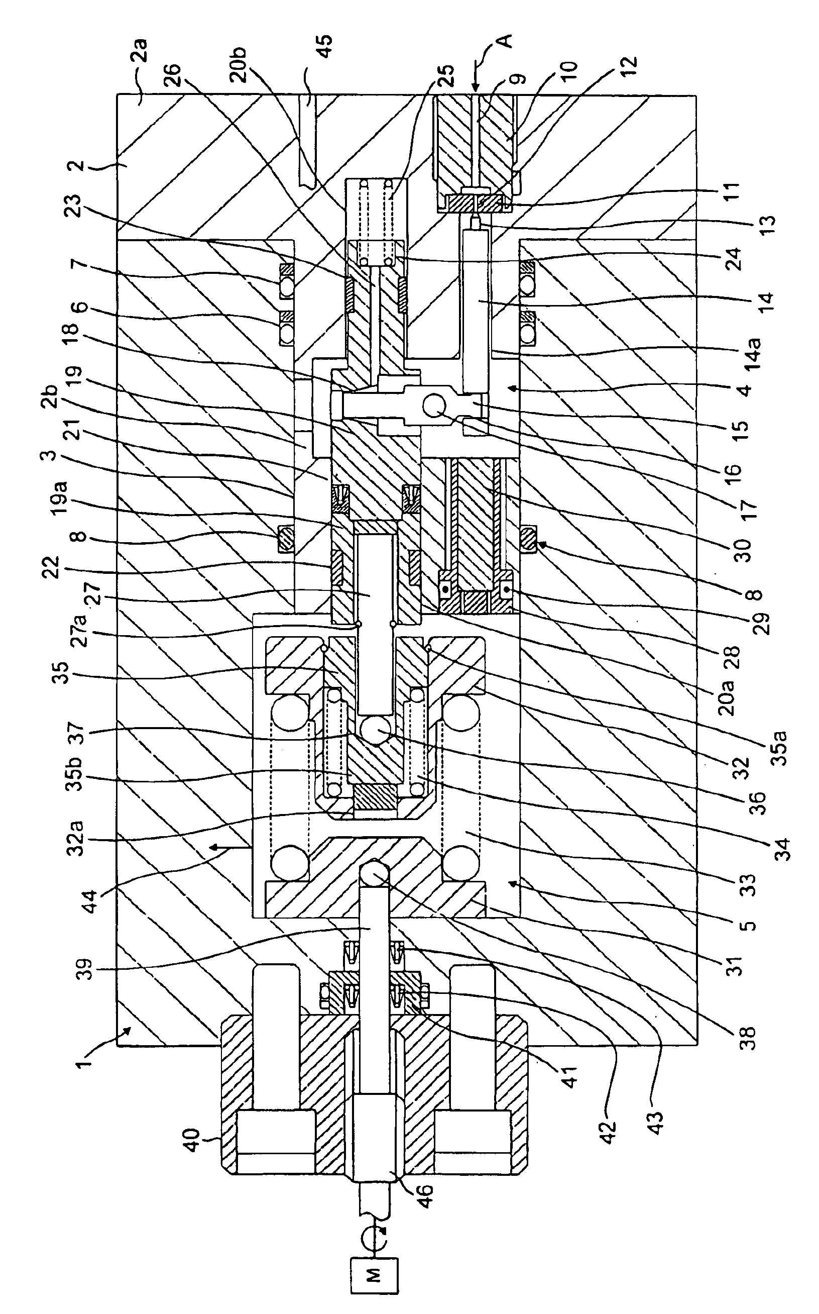
[0008]The single FIGURE illustrates a flow regulator which comprises a body principally composed of a main body part 1, which is in a generally hollow cylindrical form, and an end cap 2 comprising an end wall 2a abutting the main body part 1 and a central boss 2b which extends into a bore 3 within the main body part 1. The bore 3 defines a first chamber 4 which, as will be more particularly described later, is connected to an inlet for hydraulic fluid pressure by way of a regulating valve. The bore 3 in the main body part 1 leads to a second chamber 5, downstream of the first chamber 4. Again, as will be explained later, a piston is moveable in response to a difference in pressure between the chambers 4 and 5 and is arranged to operate the aforementioned regulating valve such that an excess pressure in chamber 4 over the pressure in chamber 5 tends to move the piston in a sense which will cause closure of the inlet regulating valve.

[0009]The flow regulator needs to be operative so t...


PUM


Abstract

A flow regulator particularly for sub-sea chemical injection at low continuous rates includes a piston moveable in response to differential pressure and controlling via a lever connection an inlet valve. The differential pressure is balanced by a dual rate spring assembly which is positionally adjustable by means of a screw-threaded adjusting rod.

Description

FIELD OF THE INVENTION[0001]The present invention relates to a liquid flow regulator and more particularly to a flow regulator which is intended to provide a substantially constant flow rate of pressurised liquid.BACKGROUND TO THE INVENTION[0002]It is known, for example from U.S. Pat. No. 4,893,649, to provide a fluid flow regulator in which a spring biased piston is disposed between two chambers of which a first is connected to an inlet and a second is connected to an outlet by way of a valve of which a closure member, such as a valve needle, is carried, typically with an intermediate spring, by the piston, there being a flow passage between the first and second chambers. The piston responds to a pressure difference between the chambers so that it tends to close the valve in response to a relative increase in pressure at the inlet. Adjustment of the flow rate may be achieved by positional adjustment of the valve seat. Flow regulators of this general type regulate the flow by means ...

Claims


Application Information

Patent Timeline
Patent Type & Authority Patents(United States)
IPC IPC(8): G05D7/01G05D7/00
CPCG05D7/0126Y10T137/7788
Inventor KIRKMAN, DOUGLAS FTIBBITTS, MATTHEW H
Owner AKER SOLUTIONS LTD
Why Eureka
Try Eureka