Reinforced structural body

a structural body and reinforcement technology, applied in the field of structural bodies, can solve the problems of reducing the overall structural performance of the part, affecting the safety of the structure, so as to achieve the effect of dissipating the energy of an accident and reinforcing the structural body

Inactive Publication Date: 2005-05-24
DOW GLOBAL TECH LLC
View PDF149 Cites 62 Cited by
  • Summary
  • Abstract
  • Description
  • Claims
  • Application Information

AI Technical Summary

Benefits of technology

[0008]The present invention is particularly useful in reinforcing a structural body, particularly of a vehicular frame rail or unibody. For example, it is quite common for frame rails of automobiles to have sections that are weakened to create crush zones to dissipate the energy of an accident and protect the occupants. The frame rails also support parts of the automobile such as the transmission. The present invention provides a way for a reinforcing material to be introduced selectively into a portion of the frame rail without compromising the crush zone or clogging the mounting holes for other components such as engines and transmission. The present invention may also be used to reinforce other components of a vehicle such as rocker panels, beams, pillars, crossbars, body mounts and the like. Furthermore, the present invention may be used for non-vehicular applications such as athletic equipment (for example, golf clubs), boats, bicycles, aircraft, trucks and trains.

Problems solved by technology

Unfortunately, this method is uncontrolled and the foam inconsistently fills the cavity from one vehicle to the next.
U.S. Pat. Nos. 5,194,199, 5,866,052 and 6,062,624 disclose yet another way of reinforcing structural bodies by inserting a pre-formed cured structural foam part into the structural body However, this approach relies on the use of an expandable polyurethane or epoxy resin to adhere the structural part into place, which resin detracts from the overall structural performance of the part.
Furthermore, the integrity of the structural part-structural body bond can be compromised due to the inconsistency of the bake ovens used to cure the adhesive.

Method used


Image

  • Reinforced structural body
  • Reinforced structural body

Examples


example 1

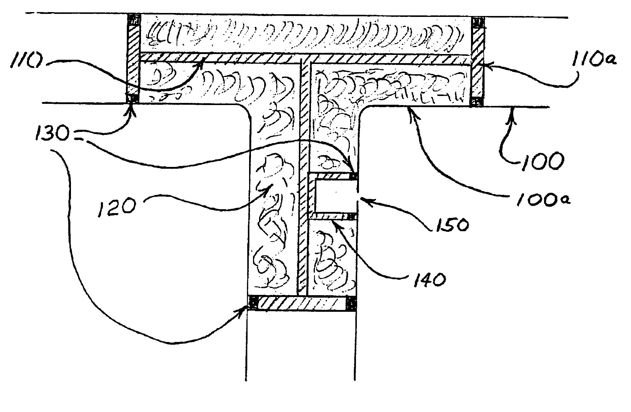
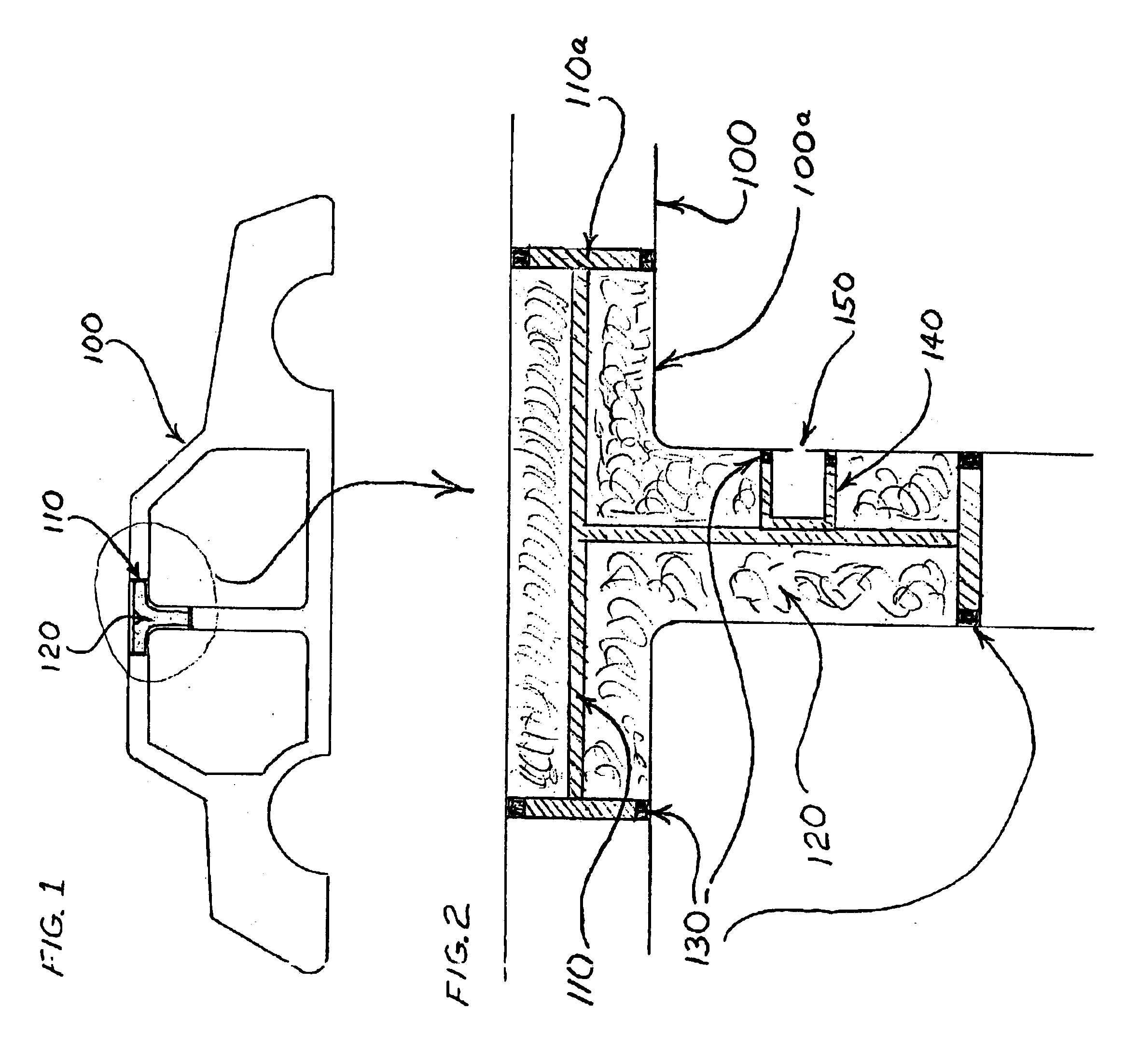
[0022]A VYDYNE 30% volume-to-volume glass filled nylon 66 insert is inserted and held mechanically into a first frame rail half with a clip using a locating hole in the first frame rail half. The insert, which is coated with a 2-mm coating BETABRACE 85076 expandable epoxy foam adhesive, is designed to maximize the amount of foam that contacts the frame rail directly.

[0023]A second frame rail half is then welded to the first frame rail half. The welded frame rail is then e-coated and the e-coat liquids flow freely through all the cavities within frame rail. The welded frame rail is then baked to a temperature sufficient to cure the e-coating and to seal the insert together with the frame rail by way of the concomitantly cured resin.

[0024]BETAFOAM 88100 isocyanate and BETAFOAM 88124 resin are injected into the inner cavity and allowed to cure forming a frame rail having reinforcing solely within the confines of the insert and the portion of the frame to which it is inserted.


PUM

PropertyMeasurementUnit
thermoplasticaaaaaaaaaa
structural strengthaaaaaaaaaa
rigidityaaaaaaaaaa

Abstract

The present invention describes a hollow structural body such as an automotive unibody or frame rail that is reinforced with a reinforcing material such as a polyurethane foam by inserting into a portion of the structural body a bulkhead-containing insert, which, in combination with the structural body at the place of insertion, creates a containment region for the reinforcing material. Uncured reinforcing material can then be added to the containment region and cured.The present invention solves a problem in the art by providing structural reinforcement to be easily and precisely placed within the structural body to provide, for example, enhanced crash resistance or improvements in acoustical properties.

Description

CROSS-REFERENCE STATEMENT[0001]This application claims the benefit of U.S. Provisional Application No. 60 / 351,088, filed Jan. 22, 2002.FIELD OF THE INVENTION[0002]The invention relates to a structural body containing a structural reinforcing material. In particular the invention relates to reinforced structural, sealing, and acoustical vehicular bodies such as reinforced frame rails and unibodies.BACKGROUND OF THE INVENTION[0003]A hollow member (structural body) of a vehicle is often filled with foam to seal, dampen noise, and to impart structural strength and rigidity or acoustical properties. Typically, a structural body is filled with a foam such as polyurethane by introducing fluid reactants into a region that it is desired to reinforce (that is, a reinforcing region) and allowing the foam to react and fill the reinforcing region. Unfortunately, this method is uncontrolled and the foam inconsistently fills the cavity from one vehicle to the next. The method, in many instances, a...

Claims


Application Information

Patent Timeline
Patent Type & Authority Patents(United States)
IPC IPC(8): B62D29/00B29C39/10B62D25/04B29K63/00B29K75/00B29K105/04B29L31/30
CPCB62D29/002B29C33/00B29C44/18B29C67/24
Inventor KROPFELD, SCOTT
Owner DOW GLOBAL TECH LLC
Why Eureka
Try Eureka