Cable end connector assembly having locking member

Inactive Publication Date: 2005-05-24
HON HAI PRECISION IND CO LTD
View PDF12 Cites 17 Cited by
  • Summary
  • Abstract
  • Description
  • Claims
  • Application Information

AI Technical Summary

Benefits of technology

[0008]An object of the present invention is to provide a cable end connector assembly having an improved locking member having relatively big displacement for locking / unlocking the cable end connector assembly with / from a complementary connector more conveniently.

Problems solved by technology

However, the locking member is a cantilevered type structure, the vertical distance between a locking position and a releasing position of the locking portion is relatively small, thereby adversely affecting the engagement and disengagement between the Serial ATA connector and the complementary connector.

Method used


Image

  • Cable end connector assembly having locking member
  • Cable end connector assembly having locking member
  • Cable end connector assembly having locking member

Examples


Embodiment Construction

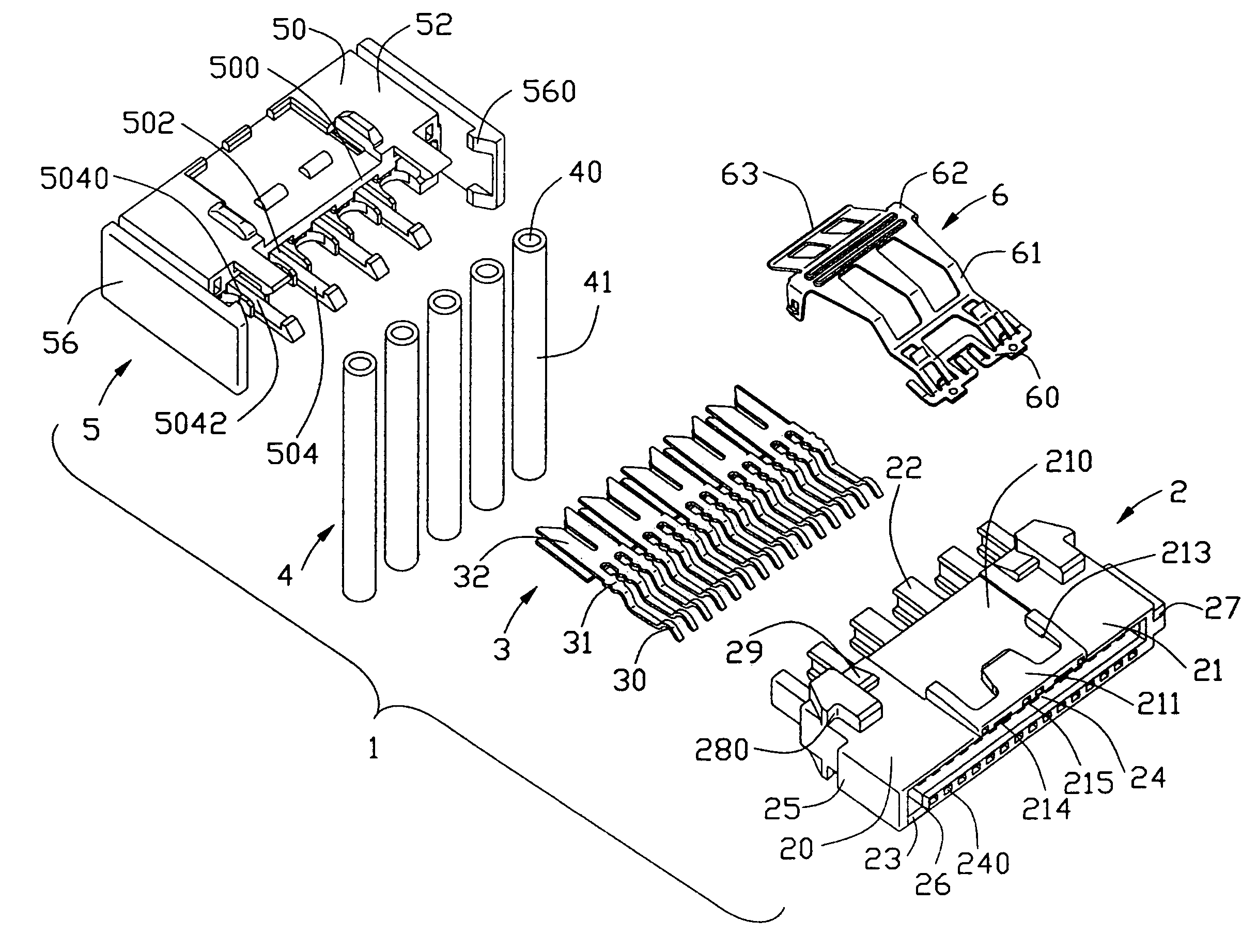
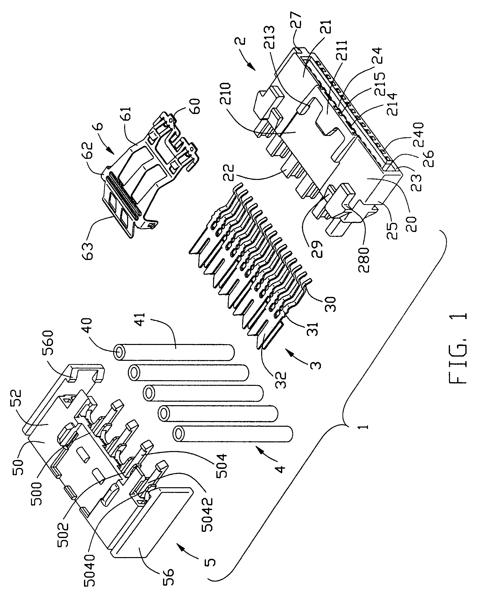
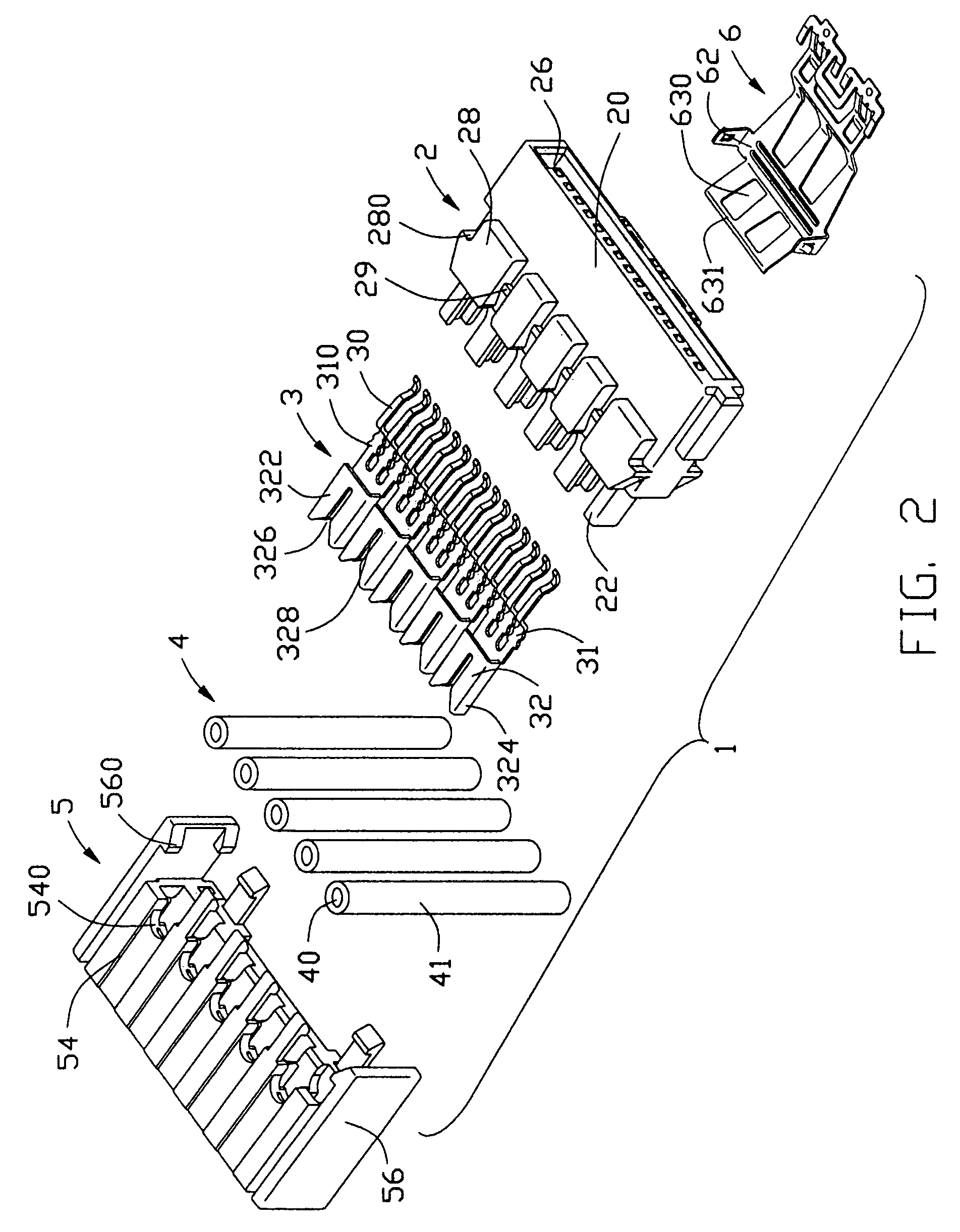
[0022]Referring to FIGS. 1–4, a cable end connector assembly 1 in accordance with the present invention comprises an insulative housing 2, a plurality of contacts 3, a plurality of wires 4, an insulative cover 5 and a locking member 6.

[0023]Referring to FIGS. 1–4 in conjunction with FIGS. 9–15, the insulative housing 2 comprises a front engaging portion 20 and a rear terminating portion 22. The front engaging portion 20 comprises an upper wall 21, a lower wall 23 opposite to the upper wall 21, and a pair of sidewalls 25 connecting with the upper wall 21 and the lower wall 23. A guiding projection 27 projects outwardly from one sidewall 25 for guiding a proper insertion of a complementary connector. An L-shaped receiving space 26 is defined between the upper and the lower walls 21, 23. A block 24 is formed on the lower wall 23 and protrudes into the receiving space 26. The block 24 defines a plurality of passageways 240. The upper wall 21 defines a depression 210 on an upper surface ...


PUM


Abstract

A cable end connector assembly (1) includes an insulative housing (2) including a front engaging portion (20) and a rear terminating portion (22), a number of IDC contacts (3) received in the insulative housing, a number of wires (4) electrically connecting with corresponding contacts, a cover (5) mechanically mounted to the terminating portion of the insulative housing, and a locking member (6). The cover defines a pair of passages (526). The locking member includes a retaining portion (60) secured with the engaging portion of the insulative housing, a pressing portion (62) received in the passages of the cover, a pressing portion (63) engaged with the cover and a pair of latch sections (610) located close to the retaining portion. The pressing portion moves downwardly toward the cover under a pressing force and creates a vertical displacement to the latch sections.

Description

CROSS-REFERENCE TO RELATED APPLICATIONS[0001]This application is related to U.S. patent application Ser. No. 10 / 397,446 filed on Mar. 25, 2003, invented by George Lee, entitled “CABLE CONNECTOR ASSEMBLY WITH LATCHING MEANS”, and Ser. No. 10 / 776,111 filed on Feb. 10, 2004, invented by Jerry Wu, entitled “CABLE END CONNECTOR ASSEMBLY HAVING LOCKING MEMBER”, both of which are assigned to the same assignee as this application.BACKGROUND OF THE INVENTION[0002]1. Field of the Invention[0003]The present invention relates to a cable end connector assembly, and particularly to a cable end connector assembly having a locking member for locking with a complementary connector.[0004]2. Description of Related Art[0005]There exists in the art an electrical connector known as a Serial Advanced Technology Attachment (Serial ATA) connector which is generally used for disk drives and storage peripherals. Especially, the Serial ATA connectors according to the Serial ATA standard are featured in fewer e...

Claims


Application Information

Patent Timeline
IPC IPC(8): H01R4/24
CPCH01R4/2433
Inventor WU, JERRY
Owner HON HAI PRECISION IND CO LTD
Why Eureka
Try Eureka