
Movable finger for prostheses, upper extremity prostheses using this movable finger, and movable finger controller

Inactive Publication Date: 2005-05-24
HARADA ELECTRONICS +2
View PDF13 Cites 111 Cited by
  • Summary
  • Abstract
  • Description
  • Claims
  • Application Information

AI Technical Summary

Benefits of technology

[0018]According to the upper extremity prosthesis of the invention, the bases may be attached to the back of the hand, alternatively the palm of the hand in the curved arrangement to be elastically swung. Thus, if the movable fingers are respectively bent and the fingertips are abutted on each other when the fingertips of the movable fingers approach each other, the base is swung to release a pressing force applied to the fingertip by the abutment. As a result, even when the accuracy of attaching position of the base to the back or palm of the hand is not so high, it is possible to prevent damaging caused by the abutments of the fingertips on each other.
[0021]Thus, according to the movable finger controller of the invention, only by means of that the human wearing the upper extremity prosthesis is conscious of moving the fingers, the movable fingers of the upper extremity prosthesis can be respectively operated. By making different the overall operational state of the movable fingers based on the combination pattern of the signals from the plurality of sensors, plural kinds of operations such as object gripping, hand opening, pointing, and the like, can be carried out by the upper extremity prosthesis. In addition, the programmable logic device automatically changes the combination of logical circuits based on the genetic algorithm, and learns adaptability between the combination pattern of the signals and the operational state of each movable finger, and output an operation command signal according to the combination pattern of the signals currently outputted from the plurality of sensors. Thus, the controller can learn the combination pattern of the signals within a very short time so as to cause the upper extremity prosthesis to carry out a desired operation.

Problems solved by technology

However, the movable finger for an active upper extremity prosthesis cannot perform any operations other than the simple one of simultaneous bending or returning of the three or five fingers by swinging only at their bases.
Consequently, there is a problem that the degree of freedom is too low compared with that of a real hand.
In addition, since it is necessary to keep the control lead made of wire attached to the back of the person in wearing the upper extremity prosthesis, there is also a problem that uncomfortableness is felt at the back.

Method used


Image

  • Movable finger for prostheses, upper extremity prostheses using this movable finger, and movable finger controller
  • Movable finger for prostheses, upper extremity prostheses using this movable finger, and movable finger controller
  • Movable finger for prostheses, upper extremity prostheses using this movable finger, and movable finger controller

Examples


Embodiment Construction

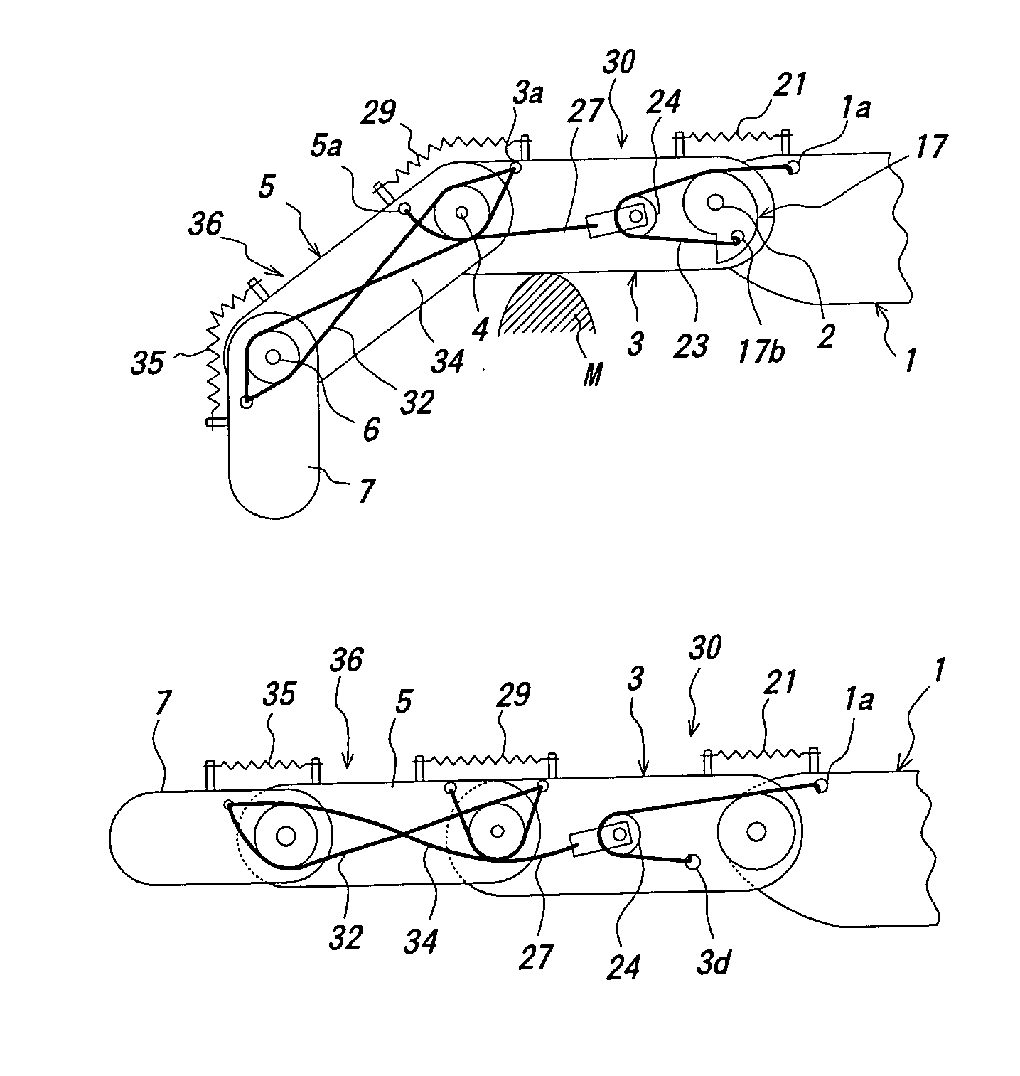
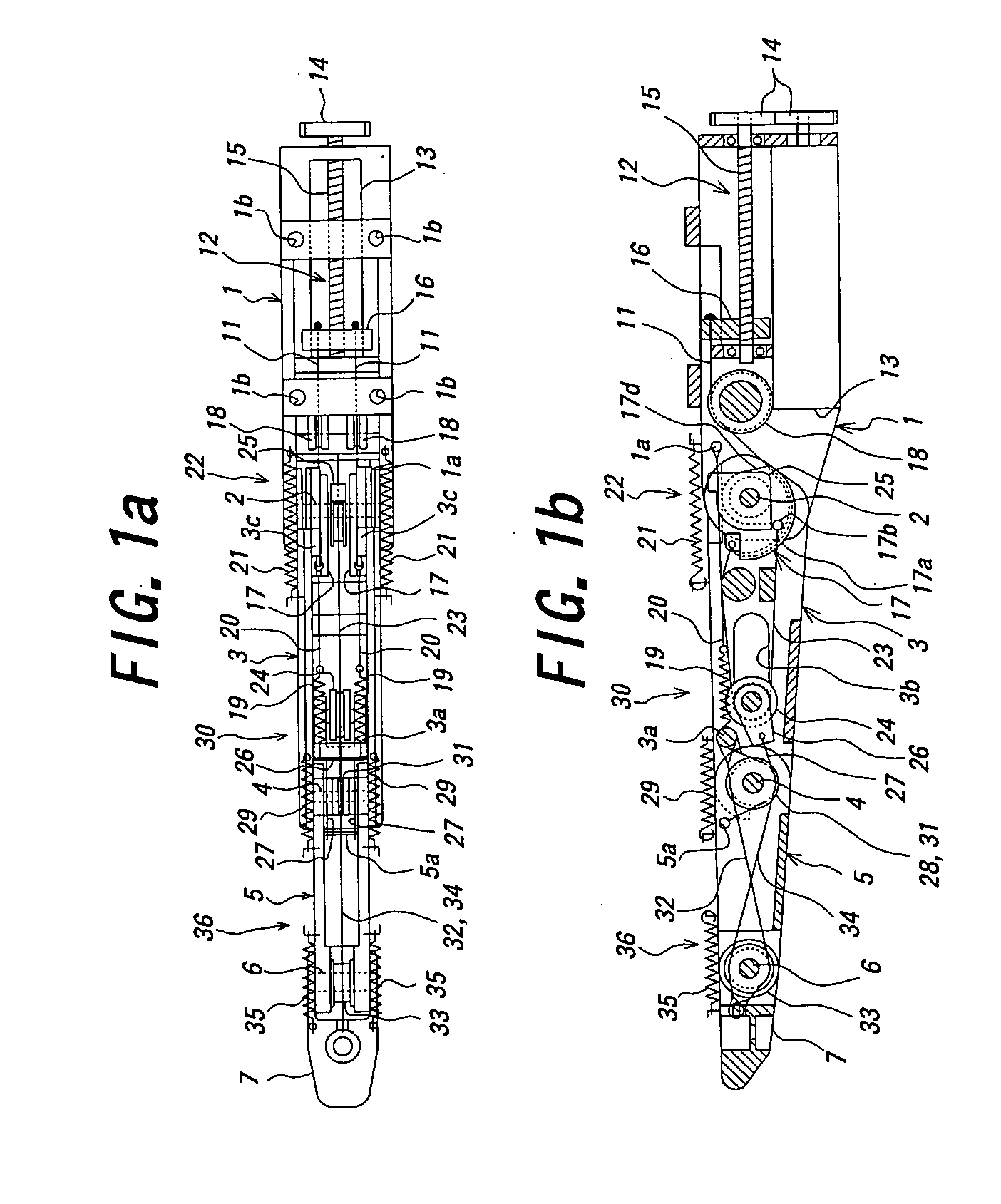
[0042]Next, the mode of the invention will be described in detail by way of embodiment with reference to the accompanying drawings. FIG. 1a is a plan view showing a movable finger for a prosthesis according to an embodiment of the invention; and FIG. 1b is a vertical sectional view of the movable finger for a prosthesis of the embodiment. The movable finger for a prosthesis of the embodiment is used as at least one of a plurality of fingers of an upper extremity prosthesis as a prosthesis, and includes: a base 1 disposed between the back and the palm of a not shown hand; a first intermediate portion 3 having a rear end swingably connected to the tip of the base 1 through a first support shaft 2; a second intermediate portion 5 having a rear end swingably connected to the tip of the first intermediate tip 3 through a second support shaft 4; and a fingertip 7 having a rear end swingably connected to the tip of the second intermediate portion 5 through a third support shaft 6.

[0043]The...


PUM


Abstract

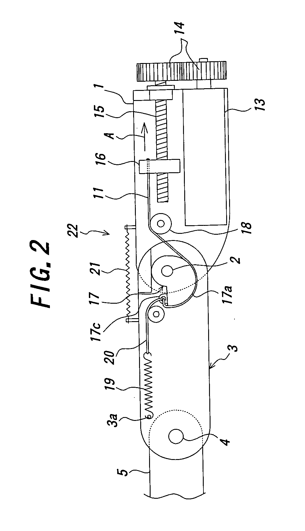
A movable finger for prostheses, having a base a first intermediate portion connected to the base, a second intermediate portion connected to the first intermediate portion, and a fingertip connected to the second intermediate portion. The prosthesis further includes a first intermediate portion bending mechanism for actuating an actuator disposed in the base to pull a first wire to turn an eccentric member, a second intermediate portion bending mechanism for pulling a second wire wound around a pulley disposed as a movable pulley in the first intermediate portion by the eccentric member, whereby the pulling and bending of the second intermediate portion is by a third wire connected to the pulley, and a fingertip bending mechanism for pulling and bending the fingertip by a fourth wire connected to the first intermediate portion, whereby the pulling and straightening is by a fifth wire.

Description

TECHNICAL FIELD[0001]This invention relates to a movable finger for a prosthesis and, more particularly, to a movable finger for an upper extremity prosthesis, an upper extremity prosthesis using the movable finger, and a controller for the movable finger.BACKGROUND ART[0002]Conventionally, as a movable finger for an upper extremity prosthesis, a movable finger for an active upper extremity prosthesis has generally been known. As to this movable finger, bases of three or five fingers, which are formed to be slightly bent in fixed shapes respectively, are swingably supported on the back or the palm of an upper extremity prosthesis. These fingers are connected to a linkage mechanism provided inside the back and the palm of the hand, a control lead made of wire is set around the back of a person wearing the upper extremity prosthesis, one end of the control lead being connected to the linkage mechanism. The other end of the control lead is connected to an arm of a side opposite to the ...

Claims


Application Information

Patent Timeline
IPC IPC(8): A61F2/50A61F2/68A61F2/58B25J15/00A61F2/00A61F2/72A61F2/70A61F2/56A61F2/54
CPCA61F2/583A61F2/586A61F2/68B25J15/0009A61F2/72A61F2002/30322A61F2002/30523A61F2002/5072A61F2002/701A61F2002/704A61F2220/0025A61F2250/0026A61F2002/30525A61F2/70
Inventor HIGUCHI, TETSUYAHARADA, MASAHIDE
Owner HARADA ELECTRONICS
Learn More