Circuit for selectively enabling and disabling coils of a multi-coil array
What is Al technical title?
Al technical title is built by PatSnap Al team. It summarizes the technical point description of the patent document.
a multi-coil array and circuit technology, applied in the field of peripheral vasculature imaging with nuclear magnetic resonance, can solve the problems of limited field of view, trade-off between resolution, relative insensitivity of remote coils to individual spins,
Inactive Publication Date: 2005-05-24
BAYER HEALTHCARE LLC
View PDF1 Cites 48 Cited by
Summary
Abstract
Description
Claims
Application Information
AI Technical Summary
This helps you quickly interpret patents by identifying the three key elements:
Problems solved by technology
Method used
Benefits of technology
Problems solved by technology
Because of their large size the remote coils suffer from a relative insensitivity to individual spins.
A disadvantage of the surface coil however, is its limited field of view.
Therefore, the surface coil necessarily restricts the field of view and inevitably leads to a tradeoff between resolution and field of view.
Generally, larger coils induce greater patient sample losses and therefore have a larger noise component, while smaller coils have lower noise but in turn restrict the field of view to a smaller region.
While an increased number of surface coils may be used to increase the field of view, NMR system scanners typically have a limited number of preamplifier inputs.
The number of preamplifier inputs is therefore a design limitation in the design of phased array surface coils.
A disadvantage of known phased array surface coils, therefore, is that the surface coil array may include only as many coils as can be directly connected to the preamplifiers of the system scanner.
This technique, however, requires excessive scan room intervention.
This may increase examination time and increase the likelihood of a patient rejecting the procedure.
Method used
Image
Click on the blue label to locate the original text in one second.
Reading with bidirectional positioning of images and text.
Examples
Embodiment Construction
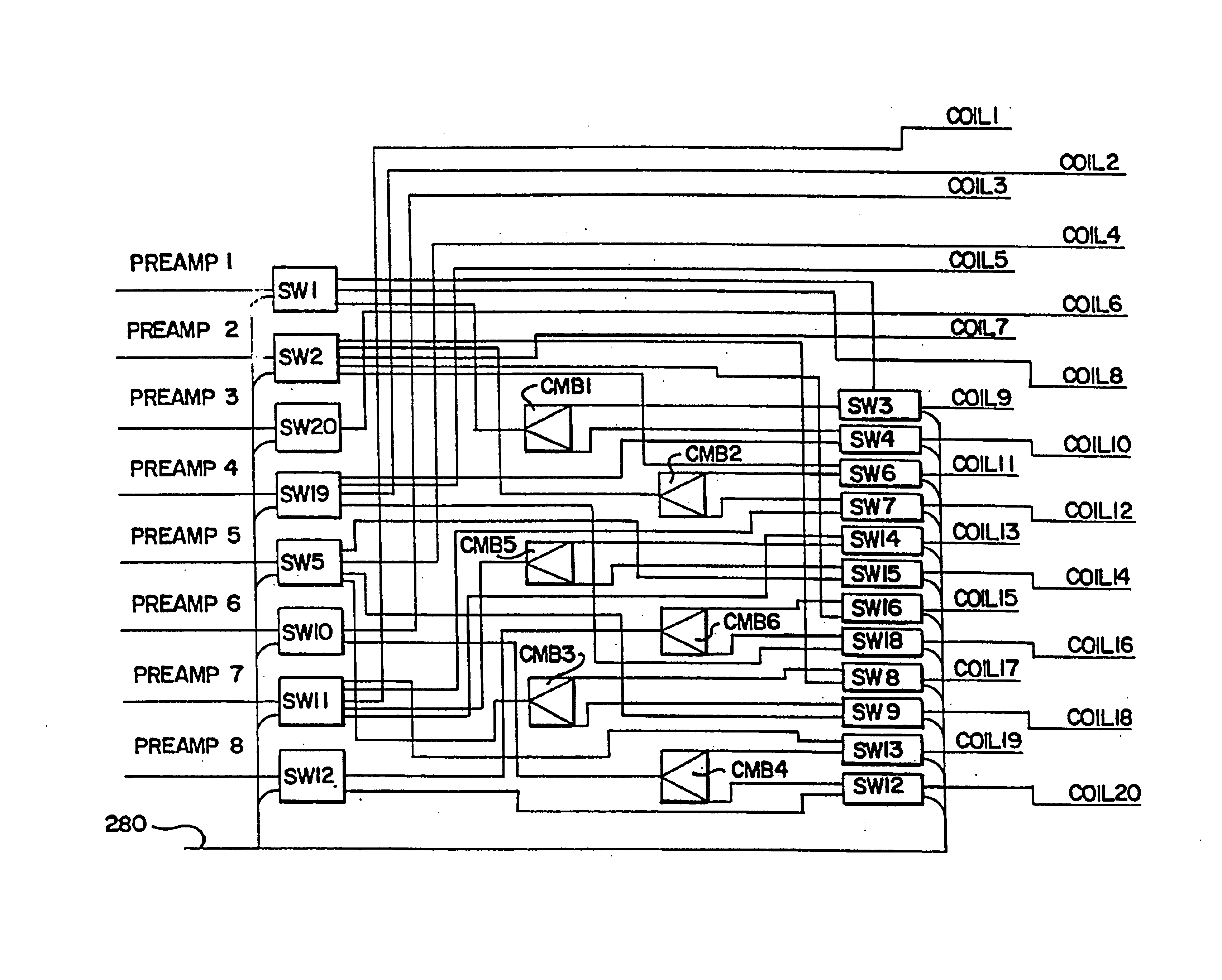
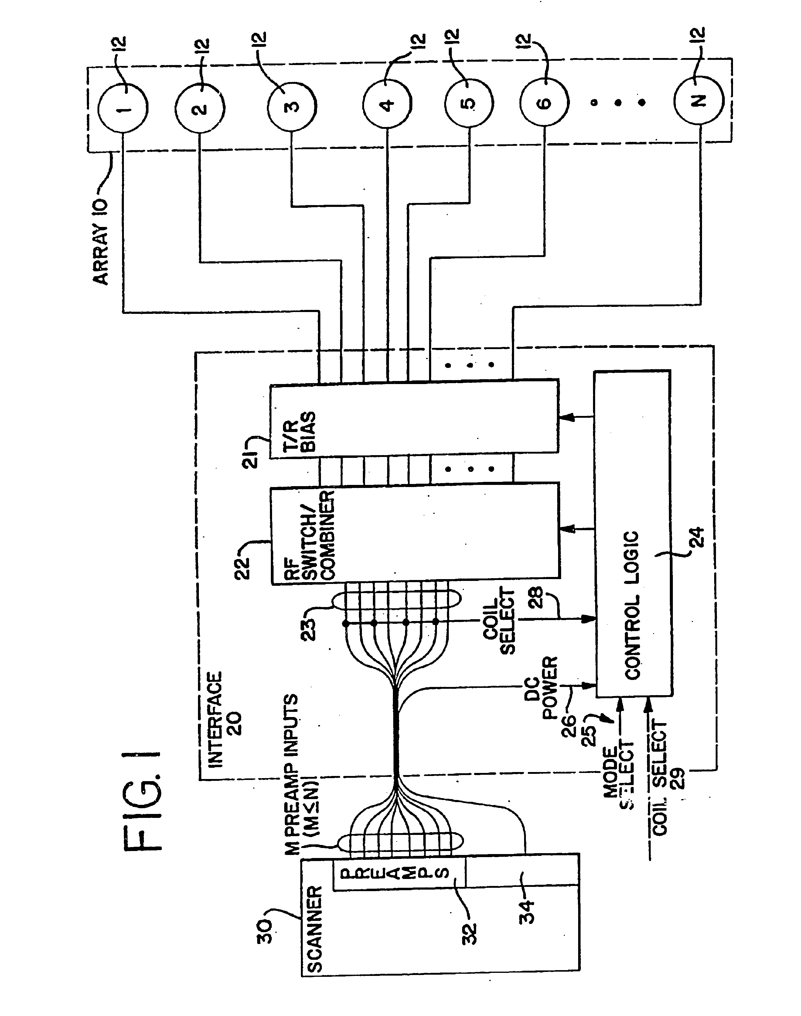
[0025]FIG. 1 is a schematic diagram of a system for receiving an NMR response signal in accordance with a preferred embodiment of the present invention. The system includes a surface coil array 10 that is connected by an interface 20 to an NMR scanner 30. The surface coil array 10 includes a number, N, of surface coils 12. Each of the surface coils 12 is electrically connected through a transmit / receive (“T / R”) bias circuit 21 to an RF switch / combiner 22 in the interface 20. The RF switch / combiner 22 has a plurality of outputs 23 that are connected to a plurality of receiver preamplifiers 32 in the NMR scanner 30.
[0026]The interface 20 also includes a control logic circuit 24, which is coupled to and controls the RF switch / combiner 22 and the T / R bias 21. The control logic circuit 24 has three inputs. The first input is a DC power input 26, which is provided by a power supply 34 in the NMR scanner 30. The second input is a coil select input 28. The third input is a mode select put 2...
PUM
Abstract
A circuit for selectively disabling and enabling n-coils includes n-drivers in a totem-pole configuration. Each of the n-drivers includes two transistors whose control terminals connect at a common node. Each n-driver is used to operate one of the n-coils by being responsive at its common node to (i) a coil disable signal by activating one transistor thereof and deactivating the other transistor thereof thereby drawing current away from and thus disabling its corresponding coil and allowing current to flow through the one transistor and thus be available as a source of current to a successive one of the n-drivers and (ii) a coil enable signal by deactivating the one transistor thereof and activating the other transistor thereof thereby allowing current to flow serially through its corresponding coil and the other transistor thus enabling its corresponding coil and to be available as a source of current to the successive n-driver.
Description
CROSS-REFERENCE TO RELATED APPLICATIONS[0001]This application for patent is continuation of U.S. application Ser. No. 10 / 260,787, filed Sep. 30, 2002 now U.S. Pat. No. 6,677,755. U.S. application Ser. No. 10 / 260,787 is a divisional of U.S. application Ser. No. 10 / 015,190, filed Nov. 26, 2001 U.S. Pat. No. 6,714,012, which itself is a divisional of U.S. application Ser. No. 08 / 978,718, filed Nov. 26, 1997, now issued as U.S. Pat. No. 6,323,648 on Nov. 27, 2001. This application thus claims the benefit of the filing date of the great-grandparent application, Nov. 26, 1997.BACKGROUND OF THE INVENTION[0002]The present invention relates to nuclear magnetic resonance (“NMR”) imaging and, more particularly, to methods and apparatus for imaging the peripheral vasculature.[0003]Initially, NMR imaging systems utilized receiver coils which surrounded the entire sample (for example a human patient) that was to be image These remote coils had the advantage that the sensitivity was, to a first ap...
Claims
Application Information
Patent Timeline
Application Date:The date an application was filed.
Publication Date:The date a patent or application was officially published.
First Publication Date:The earliest publication date of a patent with the same application number.
Issue Date:Publication date of the patent grant document.
PCT Entry Date:The Entry date of PCT National Phase.
Estimated Expiry Date:The statutory expiry date of a patent right according to the Patent Law, and it is the longest term of protection that the patent right can achieve without the termination of the patent right due to other reasons(Term extension factor has been taken into account ).
Invalid Date:Actual expiry date is based on effective date or publication date of legal transaction data of invalid patent.
Patent Type & Authority Patents(United States)
IPC IPC(8): G01R33/34G01R33/3415G01V3/00
CPCG01R33/3415
Inventor BELT, KENNETH W.REICHEL, MICHAELWATRAL, J. MICHAEL