Reinforcement bar support device

Inactive Publication Date: 2005-05-31
HANCOCK KEVIN
View PDF7 Cites 12 Cited by
  • Summary
  • Abstract
  • Description
  • Claims
  • Application Information

AI Technical Summary

Benefits of technology

[0005]The present invention is a device designed to help a construction worker to efficiently suspend re-bars over a ditch at the precise locations where the hollow blocks are to be lowered to form a block wall.
[0009]The body of the re-bar holder, to form a stronger grip of the re-bar, may have a plurality of saw-tooth blades extending into the top of the body of the re-bar holder or may have an array of buttons embedded into the inside wall of the body. The re-bar holder may also incorporate a side guide shaped like an elongated half circular cylinder extending along the side aperture, the side aperture being cut off by the body with adequate spacing to easily snap a re-bar into the re-bar holder.

Problems solved by technology

This process is time consuming.
While this method did away with the use of steel tie wires, it still requires the traditional wooden board and measurements for the re-bar holders on the wooden board.

Method used


Image

  • Reinforcement bar support device
  • Reinforcement bar support device
  • Reinforcement bar support device

Examples


Embodiment Construction

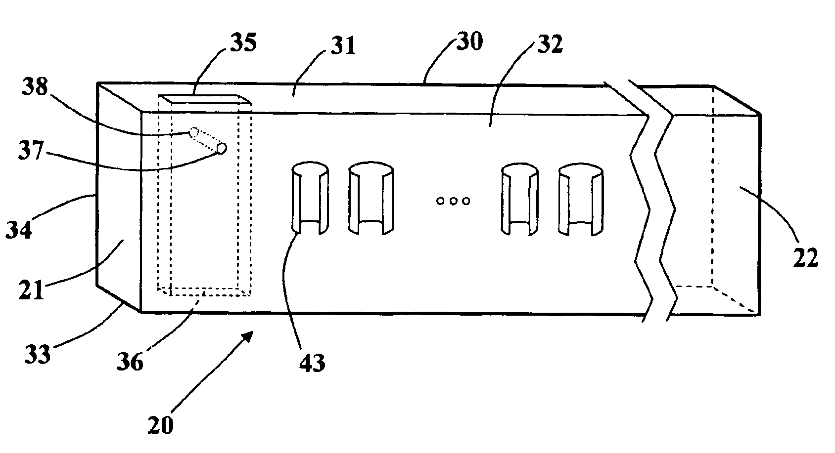
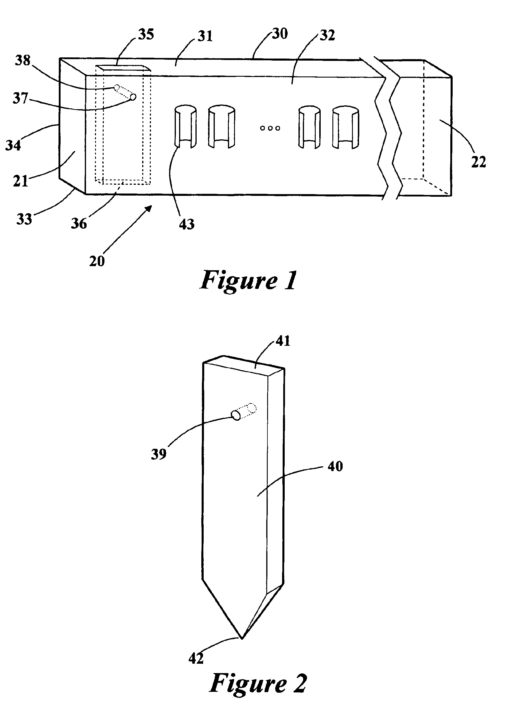
[0021]FIG. 1 illustrates the re-bar support device 20 on a base board 30. The base board 30 is hollow, preferably but not essentially made of plastic material, having a top surface 31, a first wall 32, a bottom surface 33, and a second wall 34. On the top surface 31 and the bottom surface 33 are apertures 35 and 36, usually but not essentially of rectangular shape, carved out to allow a stake 40 shown in FIG. 2 to go through these apertures. The stake 40 has a top end 41 and a sharp bottom end 42 and its shape conforms with the shape of apertures 35 and 36. Commercially available stakes are usually made of metal and are 1½ inches wide and ⅜ inch thick having a plurality of holes or apertures along the length of the stake. However, only one aperture 39 is sufficient to hold one stake to the re-bar support device 20. The aperture 39 approximately 1¼ inch from the top end 41 of the stake as shown in FIG. 2 is usually chosen for the device 20 described. The stake illustrated herein only...


PUM

PropertyMeasurementUnit
Lengthaaaaaaaaaa
Diameteraaaaaaaaaa

Abstract

A re-bar support device comprising a base board and re-bar holders to hold a plurality of re-bars spaced to fit into the holes of the hollow blocks used to build a block wall. The re-bar support device attaches to vertically standing stakes. Several re-bar support devices may be interconnected to cover the desired length of the foundation of the wall. The re-bar support device proposes several methods for easily introducing a re-bar to a re-bar holder and also discloses modifications on the internal side of the body of the re-bar support device to allow a better grip on the re-bars while concrete is poured around them during the formation of the foundation for the wall.

Description

BACKGROUND[0001]The present invention relates to an apparatus for supporting vertical steel reinforcement bar (re-bar) of various diameters during the pouring of a concrete foundation for a wall using a base board with holders attached to the base board. The holders holding the re-bars are positioned in such a way that the re-bars would allow the hollow concrete blocks to fit over them during the construction of the wall.[0002]In a typical wall construction project, a ditch must be dug out. The ditch is then filled with concrete cement forming the foundation for the wall. Hollow blocks are then set on the foundation, and cemented. Concrete is poured into the hollow block to provide strength. However, in order for the wall to be structurally sound, re-bars originating from the foundation and extending upwards into the wall, must be placed. Typically, the steps taken to construct a block wall is as follows:[0003]A ditch extending into the ground is dug to house the foundation of the w...

Claims


Application Information

Patent Timeline
IPC IPC(8): E02D27/02E04C5/20E04C5/16
CPCE02D27/02E04C5/20E04C5/168E04C5/167
Inventor HANCOCK, KEVIN
Owner HANCOCK KEVIN
Why Eureka
Try Eureka