Injection spraying system
- Summary
- Abstract
- Description
- Claims
- Application Information
AI Technical Summary
Benefits of technology
Problems solved by technology
Method used
Image
Examples
Embodiment Construction
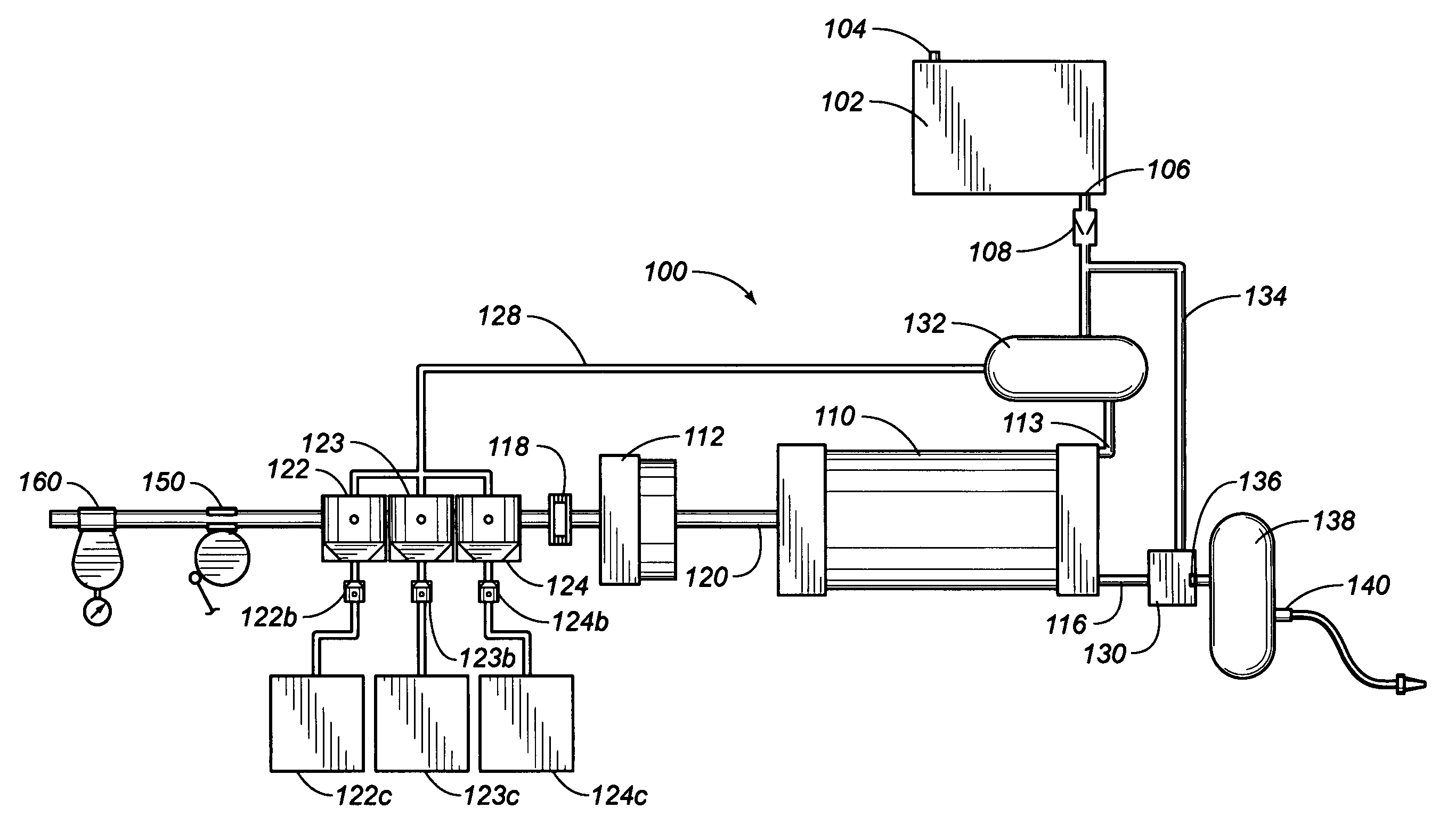
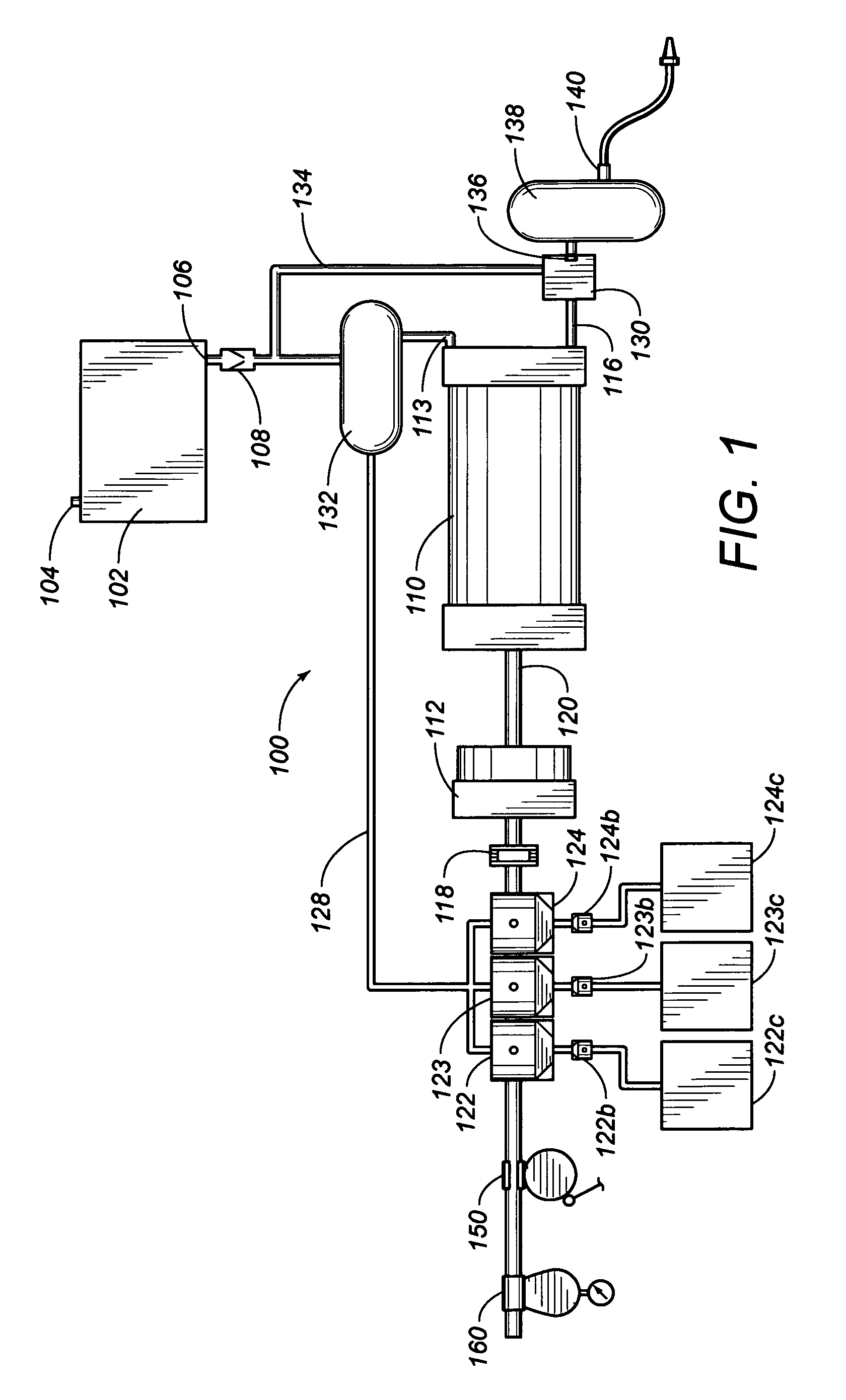
[0034]FIG. 1 shows a schematic view of the injection spraying system 100 of the present invention. The water tank 102 has an inlet 104 and an outlet 106. A check valve 108 is positioned within the outlet 106 of the water tank 102 to prevent back flow of fluid to the water tank 102. The check valve 108 has a hinged flap closing against a valve seat for a water tight seal. A mixing globe 132 is fixedly attached to the outlet 106 of the water tank 102 such that the check valve 108 is interposed between the water tank 102 and the mixing globe 132. The mixing globe 132 has a cylindrical shape so that flow of water and additives therein is tangential.
[0035]The present invention also includes a pump means 110 to pressurize water to be sprayed. The pump means 110 has an inlet pipe 113 and an output conduit 116. The inlet pipe 113 connects to the mixing globe 132 such that water flows from the water tank 102, through the check valve 108 to the mixing globe 132 and into the pump means 110. A ...
PUM
 Abstract
Description
Claims
Application Information
 - R&D
- Intellectual Property
- Life Sciences
- Materials
- Tech Scout
- Unparalleled Data Quality
- Higher Quality Content
- 60% Fewer Hallucinations
Browse by: Latest US Patents, China's latest patents, Technical Efficacy Thesaurus, Application Domain, Technology Topic, Popular Technical Reports.
© 2025 PatSnap. All rights reserved.Legal|Privacy policy|Modern Slavery Act Transparency Statement|Sitemap|About US| Contact US: help@patsnap.com


