Rotatable tool for chip removing machining and appurtenant cutting part therefor

a technology of rotating tools and cutting parts, which is applied in the direction of manufacturing tools, wrenches, wood boring tools, etc., can solve the problems of affecting the quality of the tool, the inability to integrate with the cutting part, and the risk of plastic deformation of the projections,

Inactive Publication Date: 2005-05-31
PROCTER & GAMBLE CO +1
View PDF14 Cites 72 Cited by
  • Summary
  • Abstract
  • Description
  • Claims
  • Application Information

AI Technical Summary

Benefits of technology

[0031]The loose top 2 is of a rotationally symmetrical basic shape in that it has a circular outer contour shape in connection with a substantially cylindrical or perhaps slightly rearwardly tapering (conical) envelope surface 10 as well as a conical surface 11 whose tip is directed forwards. In general, the loose top has a maximum diameter that is somewhat larger than the maximum diameter of the holder part 1. In the envelope surface, two concavely curved limiting surfaces 12 are formed that connect to the curved shape of the chip channels 3. In the front part of the loose top, cutting edges 13 are formed, which are shown schematically in the example in the form of edge lines between the cone surface 11 and the limiting surfaces 12. At the rear end thereof, the loose top 2 has a male member 14 for engagement with the seat 5. On either side of the male member 14, there are rearwardly facing thrust transmitting surfaces 15 for interaction with the surfaces 9 of the holder part.

Problems solved by technology

In modern machine tools, the holder parts are so sophisticated and expensive that for economical reasons they cannot be integrated with the cutting part, which constitutes the wearing part of the tool.
The fact that the pin is conical and exclusively axially introducable in the seat means that the resilient projections have to be deflected substantially outwards in order to be able to receive the pin, a fact that, if at all practicable, means that the projections risk being plastically (i.e., permanently) deformed.
Therefore, the concept could not be successfully applied to drilling tools, in particular tools having small diameters, because the material between the seat and the individual chip channels would become very thin and weakened.
A disadvantage of said tool is, however, that the loose top as well as the holder part has to be manufactured to a very high dimensional accuracy.
Another disadvantage is that the tool demands dismounting from the appurtenant machine in order to enable manipulation of the axial screw in connection with exchange of the loose top.
However, in this case, the loose top has to be manually turned between locking and releasing positions, something which on the one hand demands great force from the user, and on the other hand results in wear or a so-called embossing, which in the long term, impairs the ability of the holder part to center loose tops following each other in an exact way.

Method used


Image

  • Rotatable tool for chip removing machining and appurtenant cutting part therefor
  • Rotatable tool for chip removing machining and appurtenant cutting part therefor
  • Rotatable tool for chip removing machining and appurtenant cutting part therefor

Examples


Embodiment Construction

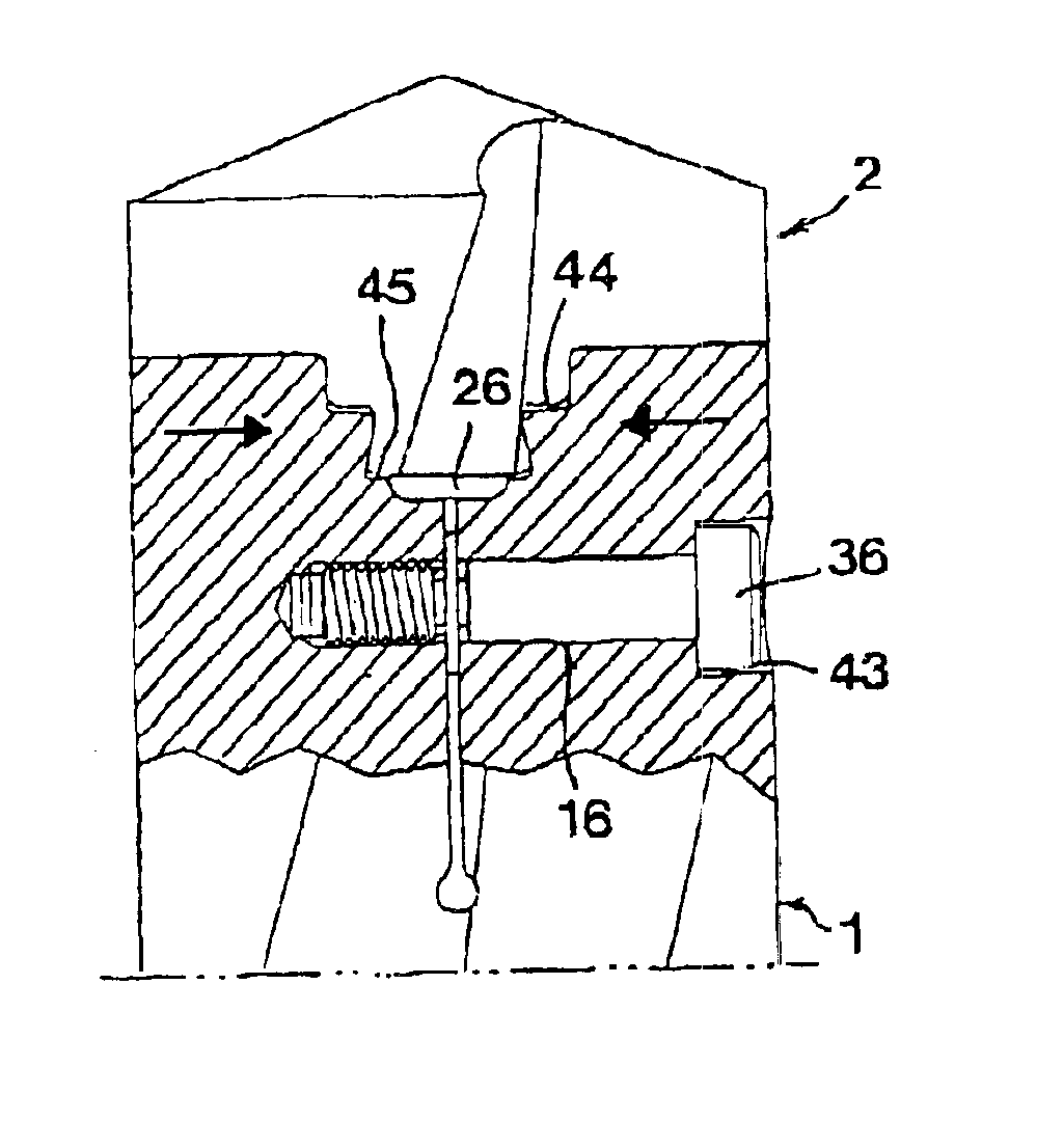
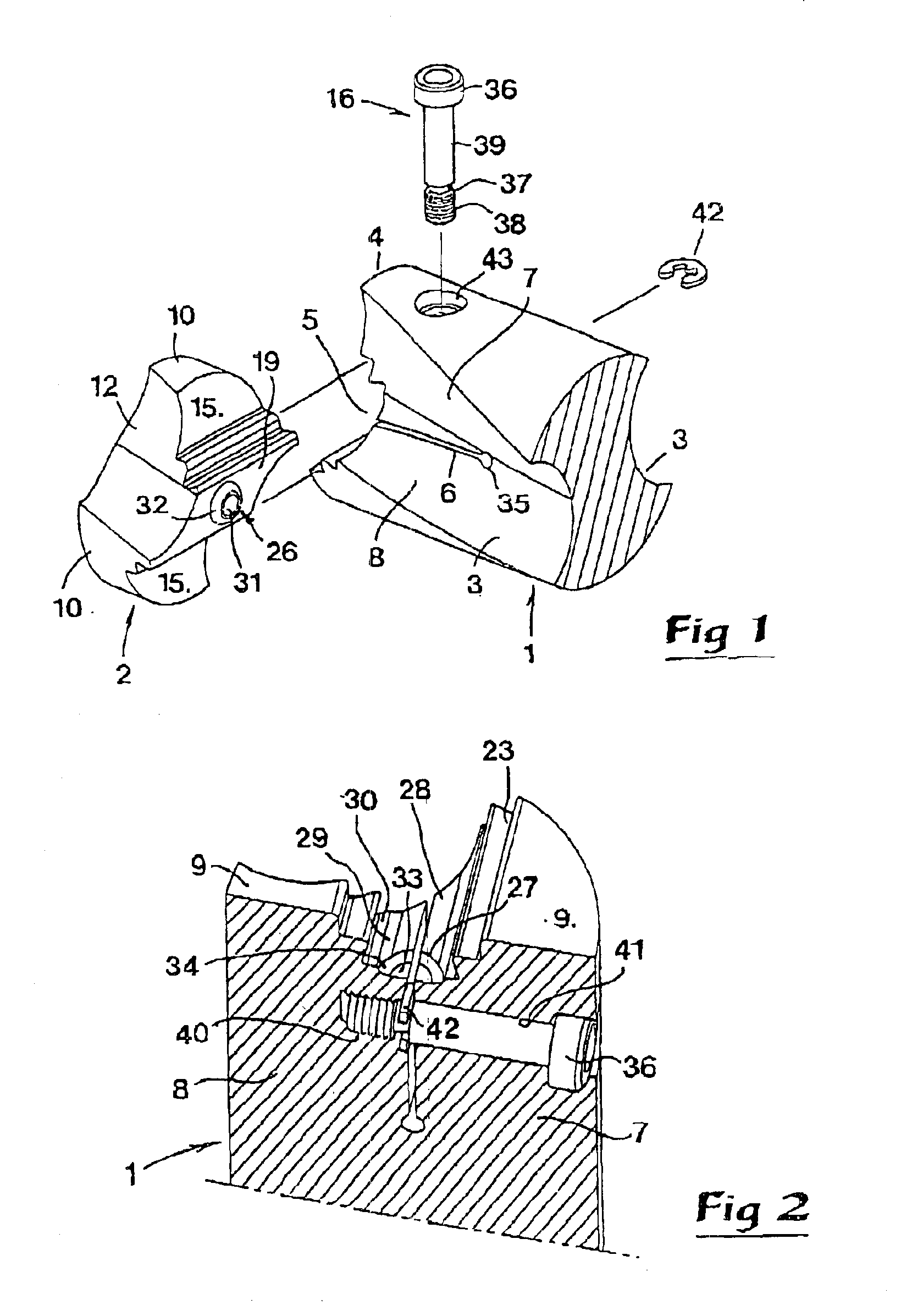
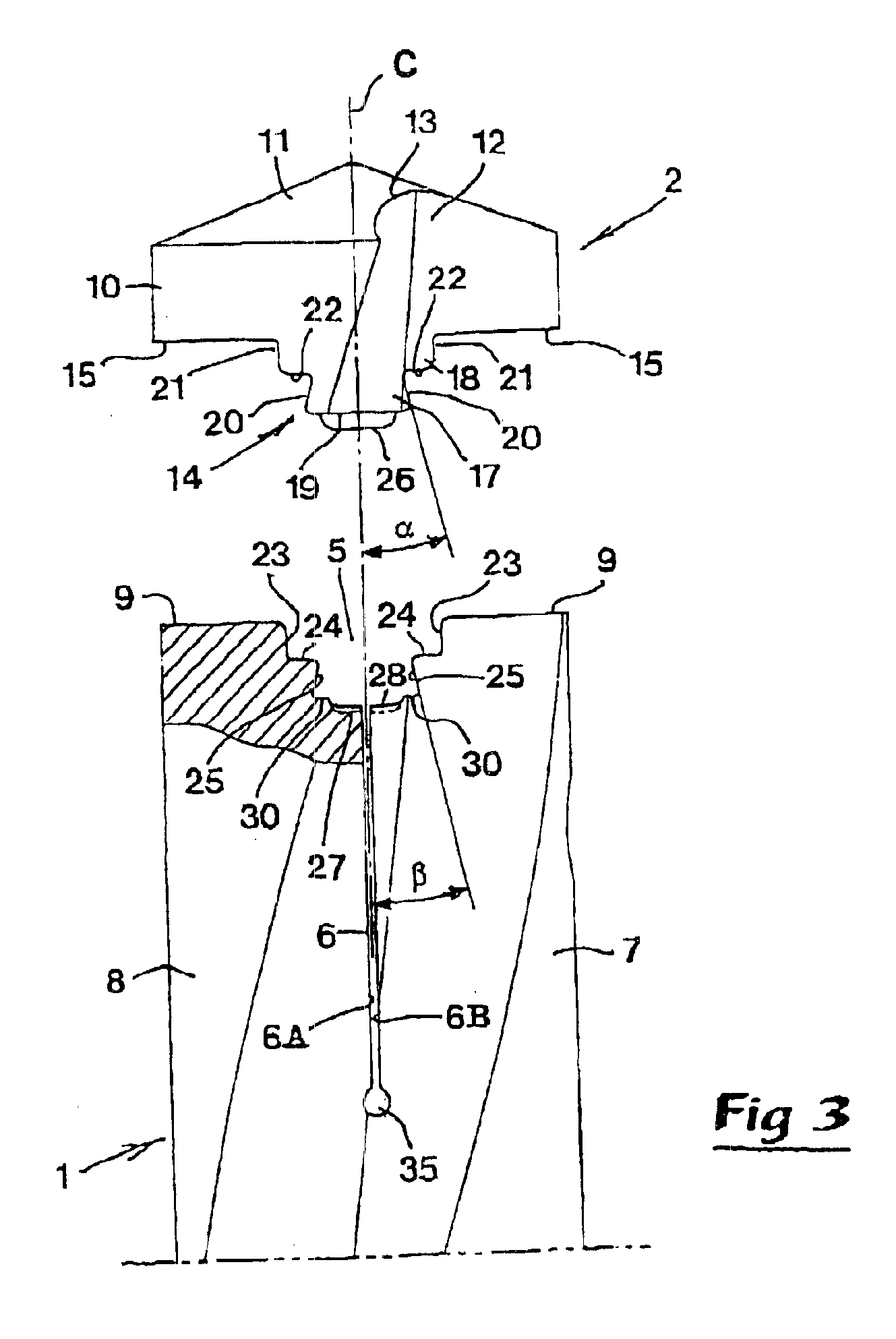
[0030]The tool illustrated in FIGS. 1-6 is in the form of a drill, which in the usual way includes a holder part or basic body 1, as well as a replaceable cutting part or loose top 2. The holder part 1 consists of a long narrow shank of a cylindrical basic shape, which in FIGS. 1-3 is shown in a cut truncated state. The shank is in a suitable way mountable in a machine, e.g. a multi-operation machine, and has two helicoidal, cross-section-wise concavely curved chip channels 3. In a front end 4 of the holder part 1, a seat 5 is formed in which a slot 6 mouths (opens), which slot separates two elastically deflectable projections 7, 8. On both sides of the seat 5, there are thrust-carrying surfaces 9.

[0031]The loose top 2 is of a rotationally symmetrical basic shape in that it has a circular outer contour shape in connection with a substantially cylindrical or perhaps slightly rearwardly tapering (conical) envelope surface 10 as well as a conical surface 11 whose tip is directed forwar...


PUM

PropertyMeasurementUnit
angleaaaaaaaaaa
angleaaaaaaaaaa
angleaaaaaaaaaa

Abstract

A rotatable tool for chip removing machining includes two parts, viz. a holder part, rotatable around a geometrical center axis, and a replaceable cutting part, which is rigidly connectable to a front end of the holder part via a male / female coupling. The coupling includes a tapering seat in the holder part and a tapering male member, protruding rearwardly from the cutting part. In the seat, there is a slot, which separates two elastically deflectable projections, that may be inwardly deflected towards each other during clamping of the male member in the seat. The male member is elongated in a radial direction, and the seat is in the form of a radial groove into and out of which the sheath body is transversely movable. The male member includes a dove-tail shaped portion received in a dove-tail shaper portion of the groove. A centering button on the male member enters a depression in the holder part to axially center the cutting part.

Description

[0001]This application claims priority under 35 U.S.C. §§119 to Patent Application Ser. No. 0103752-2 filed in Sweden on Nov. 13, 2001, the entire content of which is hereby incorporated by reference.TECHNICAL FIELD OF THE INVENTION[0002]In a first aspect, this invention relates to a rotatable tool intended for chip removing or chip forming machining, which comprises two parts, viz. a holder part, mountable in a machine and rotatable around a geometrical center axis, as well as a replaceable cutting part, which is connectable to the holder part via a male / female coupling. The coupling includes on the one hand a seat having a shape tapering in the direction axially forwards, formed in a front end of the holder part, and on the other hand a male member, protruding from a rear end of the cutting part. Like the seat, the male member has an axially tapering shape. A slot is formed in the front end portion of the holder part, which separates two elastically deflectable or resilient projec...

Claims


Application Information

Patent Timeline
Patent Type & Authority Patents(United States)
IPC IPC(8): B23B51/02B23B51/00B23C5/10B23C5/22
CPCB23B51/02B23B2251/02Y10S408/713Y10T408/9098Y10T408/78Y10T408/90987Y10T408/9097Y10T408/907B23C5/20
Inventor HANSSON, LARS-OLAHOFFMAN, CHRISTER
Owner PROCTER & GAMBLE CO
Why Eureka
Try Eureka