Optical recorder and method thereof

a technology of optical recorder and recording method, which is applied in the direction of photomechanical equipment, instruments, originals for photomechanical treatment, etc., can solve the problems of increasing manufacturing costs, inconvenient operation, and inability to solve the line width, so as to reduce the time required for exposing

Inactive Publication Date: 2005-05-31
ADVANCED LCD TECH DEVMENT CENT
View PDF13 Cites 28 Cited by
  • Summary
  • Abstract
  • Description
  • Claims
  • Application Information

AI Technical Summary

Benefits of technology

[0008]An object of the present invention lies in providing an optical recorder and a method thereof, by which, even if the line width of an exposure pattern is close to the wavelength of an exposure light, a predetermined resolution can be obtained and, besides, the time required for exposing is reduced.
[0011]In such a recorder and a method, a modulated light including an amplitude-modulated light and a phase-modulated light is imaged on a surface of an object to be exposed. Therefore, in recording an exposure pattern by exposure on the object, the amplitude-modulation and the phase-modulation can be performed at the same time, thereby easily realizing a high resolution like a phase-shift mask and reduction in exposure time. Since it is easy to control an amount of modulation, modulations of a phase and an amplitude can be readily set to an optimum amount. Also, there is fundamentally no need, as heretofore, to exchange exposure masks every time the exposure pattern is changed.

Problems solved by technology

However, in case a line width of an exposure pattern is close to the wavelength of an exposure light, the line width was not resolved because of a limitation due to a diffraction of light.
However, in a phase-shift mask, it is necessary to form a phase-modulated layer with a highly accurate thickness on a mask base, and in case the phase-modulated layer and an amplitude-modulated layer of a patterned chrome film or the like are combined, it is necessary to overlap the phase-modulated layer and the amplitude-modulated layer with high accuracy, so that it is more difficult to manufacture the phase-shift mast than an ordinary exposure mask and caused an increase in a manufacturing cost.
Also, the laser picturing device using a spatial light modulator for amplitude modulation can draw a picture, but was inferior with respect to resolution to a device using a phase-shift mask.

Method used


Image

  • Optical recorder and method thereof
  • Optical recorder and method thereof
  • Optical recorder and method thereof

Examples


Embodiment Construction

[0025]First, in the following is explained a multiplication-type optical recorder optically combining a spatial light modulator for amplitude-modulation and a spatial light modulator for phase-modulation in series and a method thereof.

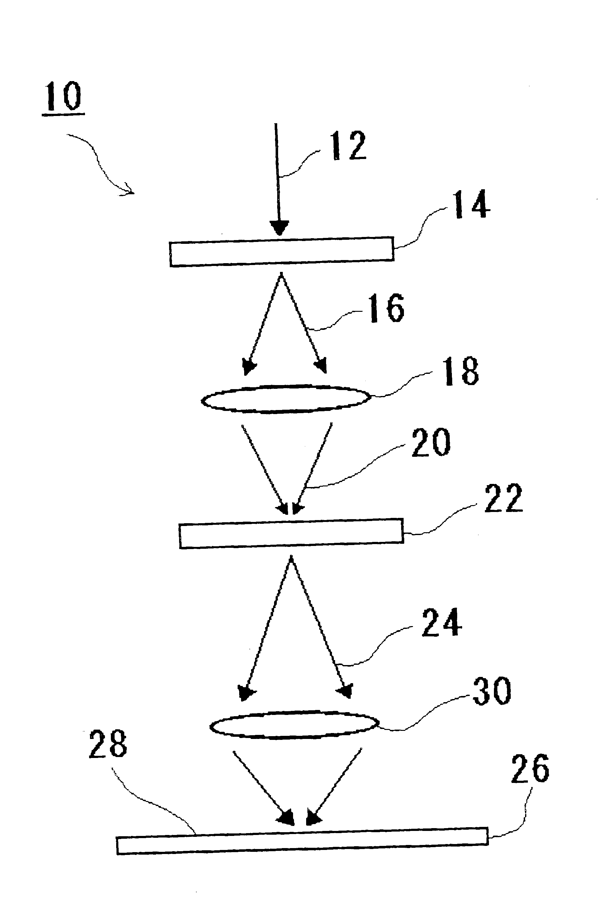
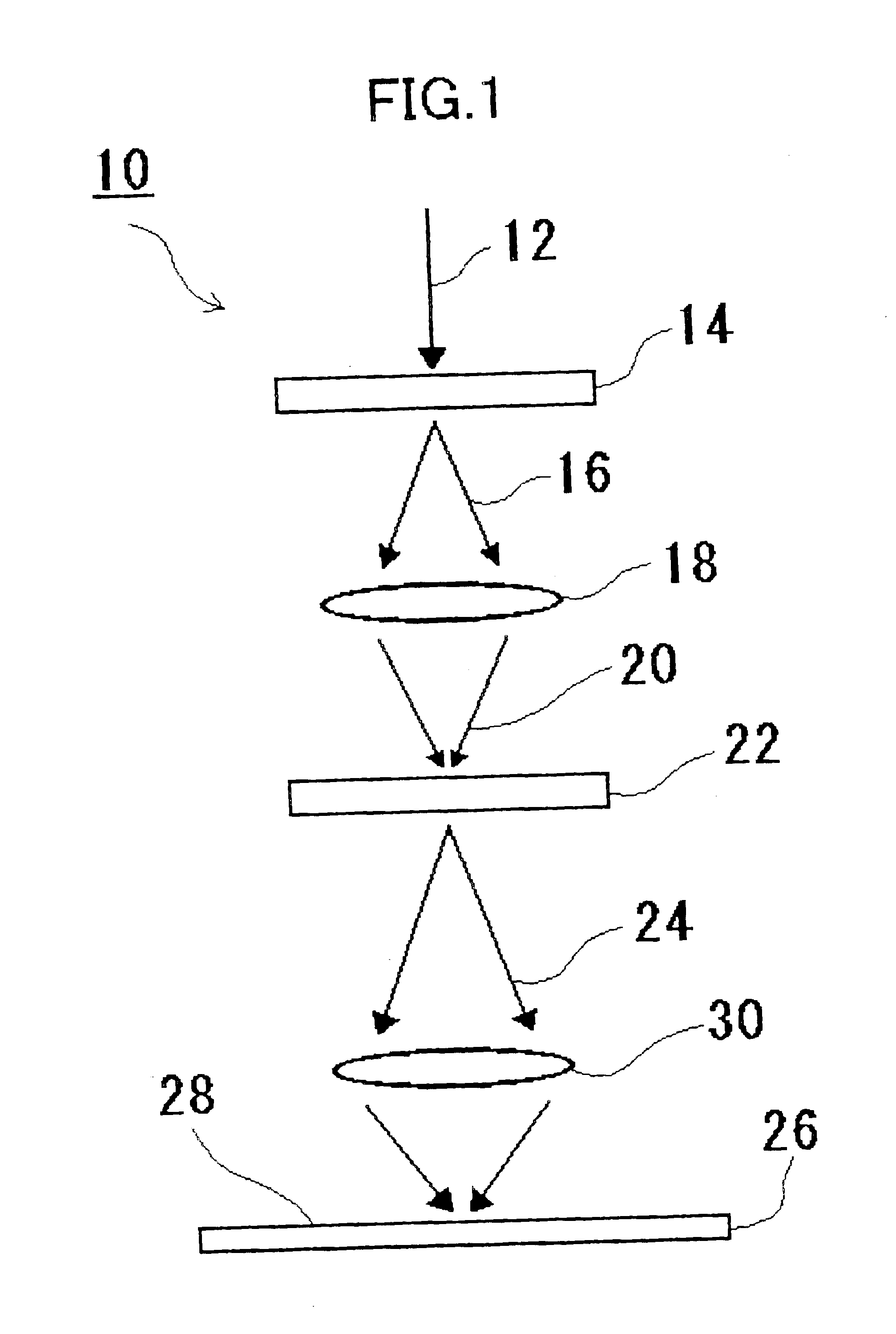
[0026]Referring to FIG. 1, the optical recorder 10 comprises: a spatial light modulator 14 (hereinafter to be called “SLM”) for amplitude-modulation of at least a part of a light 12 introduced from a light source (not shown); an imaging lens 18 for forming an image of a light 16 having transmitted through the spatial light modulator 14; a spatial light modulator 22 for phase-modulation of at least a part of a light 20 imaged by the imaging lens 18; and an imaging lens 30 for forming an image of a light 24 having transmitted through the spatial light modulator 22 on a surface 28 of an object 26 to be exposed.

[0027]As a light source for exposure, as in case of an ordinary projection exposure device, an i-line and a g-line of an extra high pressure mercur...


PUM

PropertyMeasurementUnit
diameteraaaaaaaaaa
pixel sizeaaaaaaaaaa
thicknessaaaaaaaaaa

Abstract

An optical recording art is characterized by converting a light from a light source into a modulated light including an amplitude-modulated light and a phase-modulated light and forming an image of the modulated light on a surface of an object.

Description

BACKGROUND OF THE INVENTION[0001]1. Field of the Invention[0002]This invention relates to an optical recorder and a recording method used in a process of photolithography in producing a semiconductor integrated circuit, a liquid crystal display and the like, and more particularly, to an optical recorder and a recording method suitable for forming an exposure pattern and the like having a line width substantially as large as the wavelength of an exposure light.[0003]2. Description of Related Art[0004]Among optical recorders utilizing exposure, there is an exposure device for imaging an exposure pattern on a surface of an exposed object by a projection optical system such as a lens projection or a mirror projection. However, in case a line width of an exposure pattern is close to the wavelength of an exposure light, the line width was not resolved because of a limitation due to a diffraction of light. In order to settle this problem, there is provided a method which makes the resoluti...

Claims


Application Information

Patent Timeline
Patent Type & Authority Patents(United States)
IPC IPC(8): G03F7/20G03F1/00G03F1/26H01L21/027
CPCG03F1/26G03F7/2057G03F7/70291G03F7/70283G03F7/70058H01L21/027
Inventor TANIGUCHI, YUKIO
Owner ADVANCED LCD TECH DEVMENT CENT
Why Eureka
Try Eureka