Insertable fluid warming cassette unit

Active Publication Date: 2005-05-31
STRYKER CORP
View PDF11 Cites 21 Cited by
  • Summary
  • Abstract
  • Description
  • Claims
  • Application Information

AI Technical Summary

Benefits of technology

[0011]The present invention is directed to a fluid warming cassette. The cassette has two polymeric films and at least two guide rails. A difference between this fluid warming cassette and those of the prior art is that this fluid warming cassette has a tongue section thereon. This tongue section assists the user insert the cassette into a warming unit's aperture and also not alters the spacing of a warming unit's aperture. That aperture is relatively narrow because the heating elements of the warming unit must be sufficiently close to the cassette to effectively alter the temperature of the fluid in the cassette to a desired temperature. In addition, the user can confirm if the cassette is properly inserted into the warming device's aperture by seeing that the tongue portion is sticking out of the other end of the warming device's aperture.

Problems solved by technology

In addition, the stiffener device is a guide rail for inserting the cassette into a warming unit's narrower, in relation to the apertures of Lahr et al. and Greenblatt, and non-adjustable aperture.
The stiffener device, however, is not an integral part of the cassette and can cause problems with removing and inserting the cassette into and out of the aperture of the warming device.
One of those problems can be puncturing the cassette.
A problem with Jordan et al.
's design is that the cassette is too flimsy and difficult to insert into the warming unit's aperture.
In any case, Augustine's frame unit creates further problems.
First, it does not solve the insertion problem because the quadrilateral shape is sometimes difficult to align with warming unit's aperature.
Second, it requires an expanded aperture of the warming unit to accommodate the quadrilateral frame.

Method used


Image

  • Insertable fluid warming cassette unit
  • Insertable fluid warming cassette unit
  • Insertable fluid warming cassette unit

Examples


Embodiment Construction

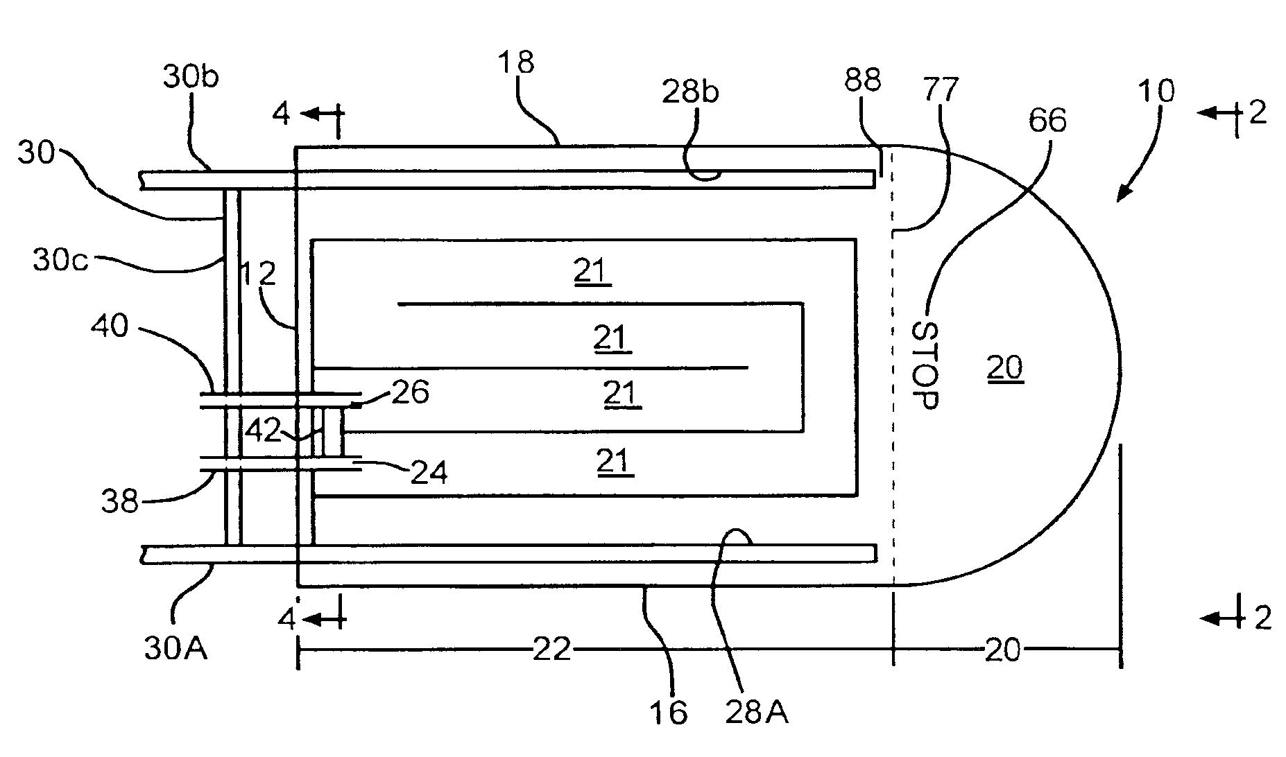
[0021]The present invention is a fluid warming cassette. Admittedly, this fluid warming cassette is a variation of the cassette disclosed by Jordan et al. because the present invention will be used in a warming unit 100 having an aperture 102, preferably the same size as the one used in and disclosed by Jordan et al.—same assignee as this invention.

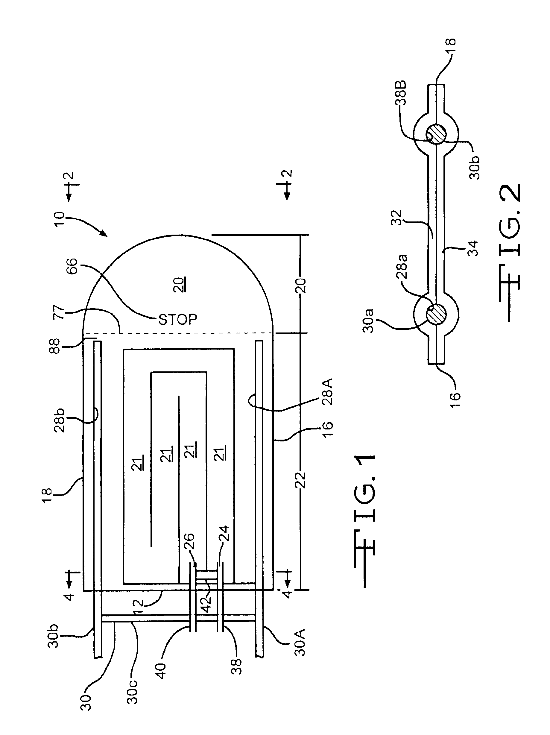
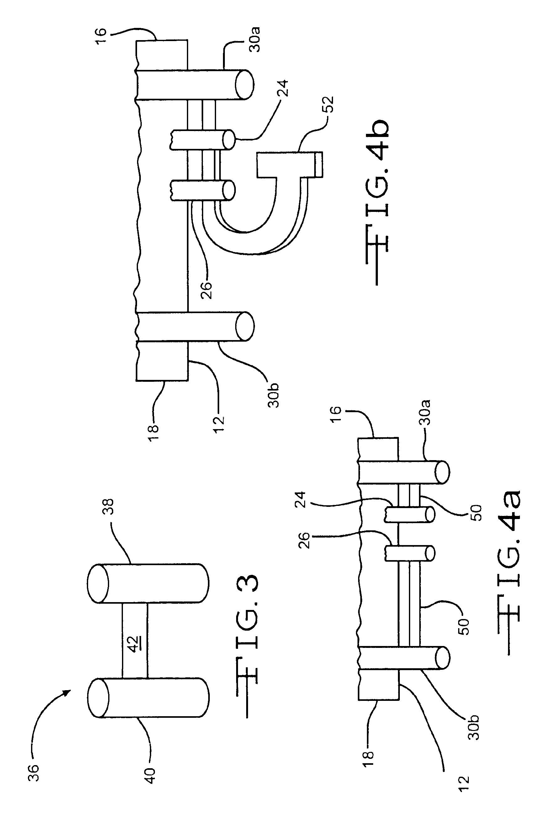
[0022]The present cassette 10 has a proximal end 12, a distal end 14, a first side 16, a second side 18, a tongue section 20 that is toward the distal end 14, a fluid path 21 within a fluid path section 22 having an inlet 24 and an outlet 26 and positioned between the tongue section 20 and the proximal end 12, and guide rail sections 28a and b. The guide rail section 28a is positioned between the first side 16 and the fluid path section 22 and the second guide rail section 28b is positioned between the second side 18 and the fluid path section 22.

[0023]The present cassette 10 is constructed from at least a guide rail system 30 and two rel...


PUM


Abstract

The present invention is directed to a fluid warming cassette. The cassette has two polymeric films and at least two guide rails. A difference between this fluid warming cassette and those of the prior art is that this fluid warming cassette has a tongue section thereon. This tongue section assists the user insert the cassette into a warming unit's aperture. That aperture is relatively narrow because the heating elements of the warming unit must be sufficiently close to the cassette to alter the temperature of the fluid in the cassette to a desired temperature. In addition, the user can confirm if the cassette is properly inserted into the warming device's aperture by seeing that the tongue portion is sticking out of the other end of the warming device's aperture.

Description

CLAIM OF PRIORITY[0001]This application claims priority to U.S. provisional patent application Ser. No. 60 / 451,731 which was filed on Mar. 4, 2003.FIELD OF THE INVENTION[0002]The present invention is directed to fluid warming cassettes.BACKGROUND OF THE INVENTION[0003]There are numerous types of fluid warming cassettes. Some of them are disclosed in U.S. Pat. No. 6,464,666 to Augustine; U.S. Pat. No. 5,875,282 to Jordan et al.; U.S. Pat. No. 4,731,072 to Aid; U.S. Pat. No. 4,707,587 to Greenblatt; and U.S. Pat. No. 3,485,245 to Lahr et al.[0004]Lahr et al. disclose a fluid warming cassette. That fluid cassette has an inlet to allow a fluid enter a counter-flow serpentine fluid path. The counter-flow serpentine fluid path is defined in the fluid warming cassette by joining portions of at least two layers of polymeric film together. The fluid exits the fluid warming cassette through at output. Inlet and outlet conduits transport the fluid to the inlet of and from the outlet of the flu...

Claims


Application Information

Patent Timeline
IPC IPC(8): A61F7/00A61M5/44
CPCA61M5/44A61F7/0085
Inventor JUSIAK, JOEL T.ZALE, DAVID J.
Owner STRYKER CORP
Why Eureka
Try Eureka