Control system for cooking appliance employing radiant cooking

a control system and cooking technology, applied in the field of cooking appliances, can solve the problems of time-consuming process, unsuitable for many other applications, and inconvenient use of dual-heating radiant ovens of this type, and achieve the effect of effective power alteration, high efficiency and high efficiency

Active Publication Date: 2005-10-27
ACP OF DELAWARE
View PDF41 Cites 16 Cited by
  • Summary
  • Abstract
  • Description
  • Claims
  • Application Information

AI Technical Summary

Benefits of technology

[0013] A particular aspect of the present invention concerns a control system for regulating a heating device of the appliance. In accordance with the most preferred embodiment of the invention, a circuit, including a relay and a triac, are arranged on a control board. The circuit is specifically designed to control the heating device to maintain a desired output level. By modifying the AC waveform delivered to the heating device, the control system can effectively alter the power delivered to the heating device in order to maintain a desired heater output. Essentially, a microprocessor is provided to turn the triac on and off at various points in the AC waveform, thereby establishing waveform chopping operations. When the control signal from the microprocessor is removed, the triac turns off at the next zero crossing of the waveform. By turning the AC voltage on at various points in the AC waveform, the triac essentially limits the power going through the controlled components which, in this case, constitute the heating device. In this manner, a relatively inexpensive, yet highly effective, way of controlling the heating device is achieved.

Problems solved by technology

While effective to a degree, the process can be time consuming and really does not result in a uniform heating of the meat, cheese and / or other toppings on the bread, nor an even toasting of the bread itself.
In addition to this potential problem, a dual radiant oven of this type is simply not suitable for many other applications.
Unfortunately, the added costs associated with such controller structure, as well as an automatic transformer, can be cost and / or weight prohibitive in connection with certain cooking appliances.

Method used


Image

  • Control system for cooking appliance employing radiant cooking
  • Control system for cooking appliance employing radiant cooking
  • Control system for cooking appliance employing radiant cooking

Examples


Embodiment Construction

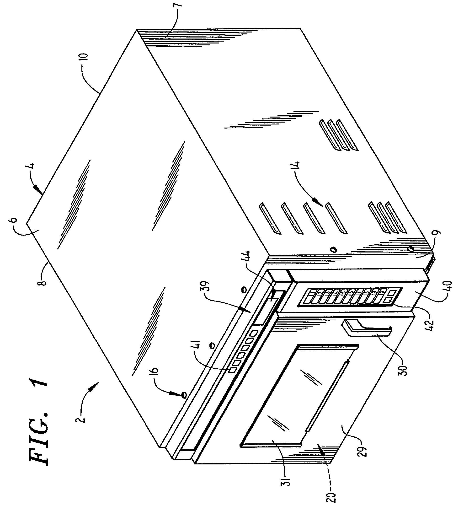
[0024] With initial reference to FIGS. 1-3, a cooking appliance constructed in accordance with the present invention is generally indicated at 2. As shown, cooking appliance 2 includes a base frame 3 to which is secured an outer cabinet shell 4 having top and opposing side panels 6-8. Cooking appliance 2 is also provided with a front face or wall 9 and a rear panel 10. Arranged at a lower portion of front wall 9 is an intake air vent 12 through which, as will be discussed more fully below, an ambient air flow enters into cabinet shell 4. In addition, cabinet shell 4 includes a plurality of air discharge vents, indicated generally at 14, arranged on side panel 7. Vents 14 enable cooling air to exit from within cooking appliance 2, thereby removing heat from within cabinet shell 4. Cabinet shell 4 is secured over base frame 3 through a plurality of fasteners 16, with the fasteners 16 arranged along front wall 9 being secured at tabs 17 (see FIG. 3).

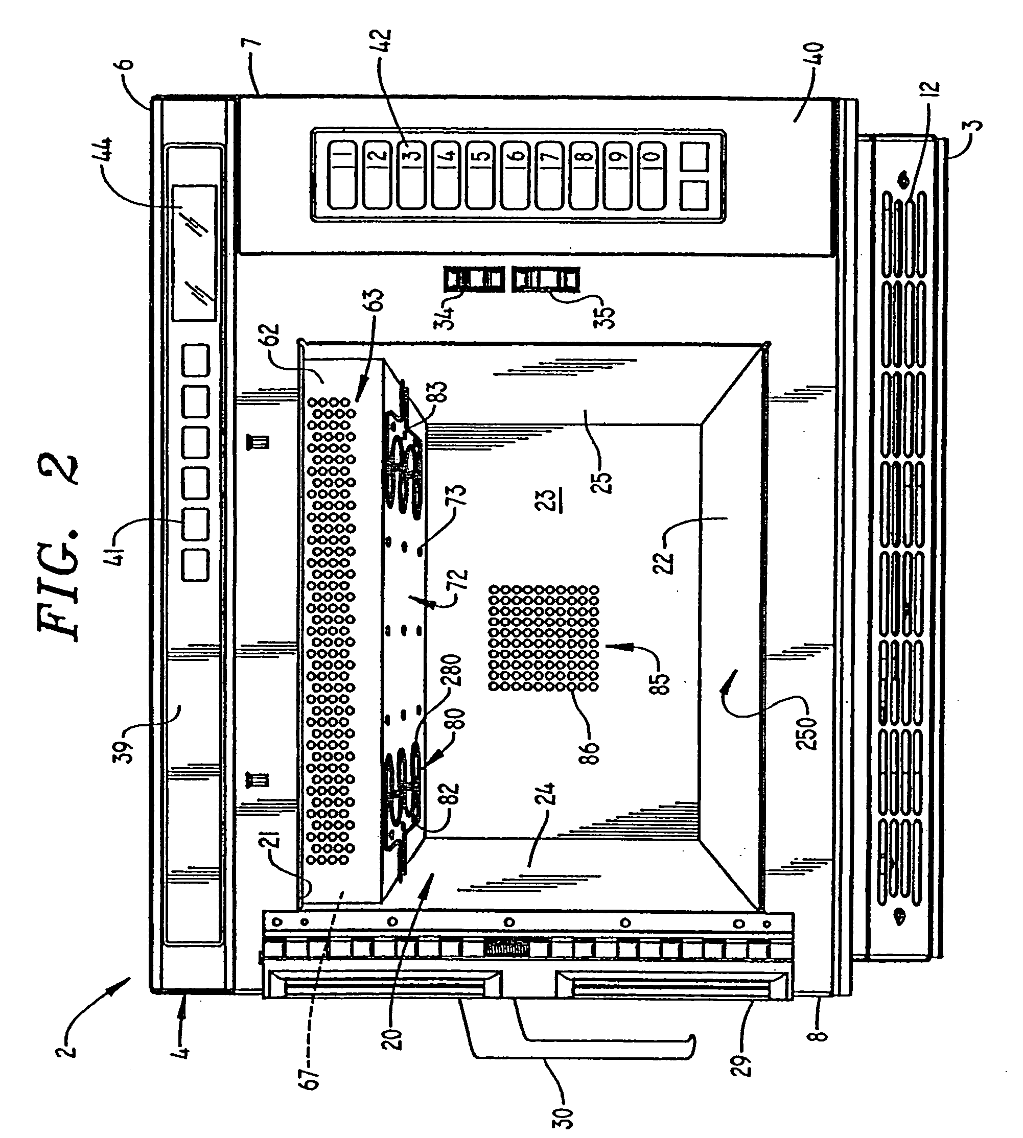
[0025] As best seen in FIG. 2, arra...


PUM


Abstract

A cooking appliance includes a heating system which is preferably capable of combining radiant, convection, microwave and conduction heating techniques to perform a cooking operation. The cooking appliance includes a convection fan and at least one heating element. A controller is provided to regulate a triac to maintain a desired heater intensity through phase angle firing. Essentially, an AC waveform provided to the heater resistor travels through the triac which is turned on by the controller at predetermined points in the AC waveform, with the delay from a zero point waveform crossing functioning to regulate the amount of power sent to the heater resistor. When the signal from the controller is removed, the triac advantageously turns off at the next zero crossing of the AC waveform such that an operationally and economically effective control system is provided.

Description

CROSS-REFERENCE TO RELATED APPLICATION [0001] The present application claims the benefit of U.S. Provisional Patent Application Ser. No. 60 / 560,280 entitled “Control System for Cooking Appliance Employing Radiant Cooking” filed Apr. 8, 2004.BACKGROUND OF THE INVENTION [0002] 1. Field of the Invention [0003] The present invention pertains to the art of cooking appliances and, more particularly, to a system for controlling the heat output of a radiant heating device in a compact cooking appliance which is preferably capable of combining radiant, convection, conduction and microwave heating techniques to perform a cooking operation and can be connected to varying voltage supplies. [0004] 2. Discussion of the Prior Art [0005] There exist a wide range of cooking appliances on the market. Many of these cooking appliances are designed for use in cooking various types of food products in different ways. For instance, where more conventional cooking appliances generally relied upon radiant e...

Claims


Application Information

Patent Timeline
Patent Type & Authority Applications(United States)
IPC IPC(8): A21B1/00A21B1/24F24C1/04F24C1/14F24C7/02F24C7/08F24C15/32H05B1/02
CPCA21B1/245H05B6/6485F24C1/04F24C1/14
Inventor GORANSON, JAMES A.
Owner ACP OF DELAWARE
Why Eureka
Try Eureka