

Self-moving cleaner
a self-moving, cleaner technology, applied in the direction of vehicle position/course/altitude control, process and machine control, instruments, etc., can solve the problems of increased cost, complex enclosure structure, and complicated cleaning process
- Summary
- Abstract
- Description
- Claims
- Application Information
AI Technical Summary
Problems solved by technology
Method used
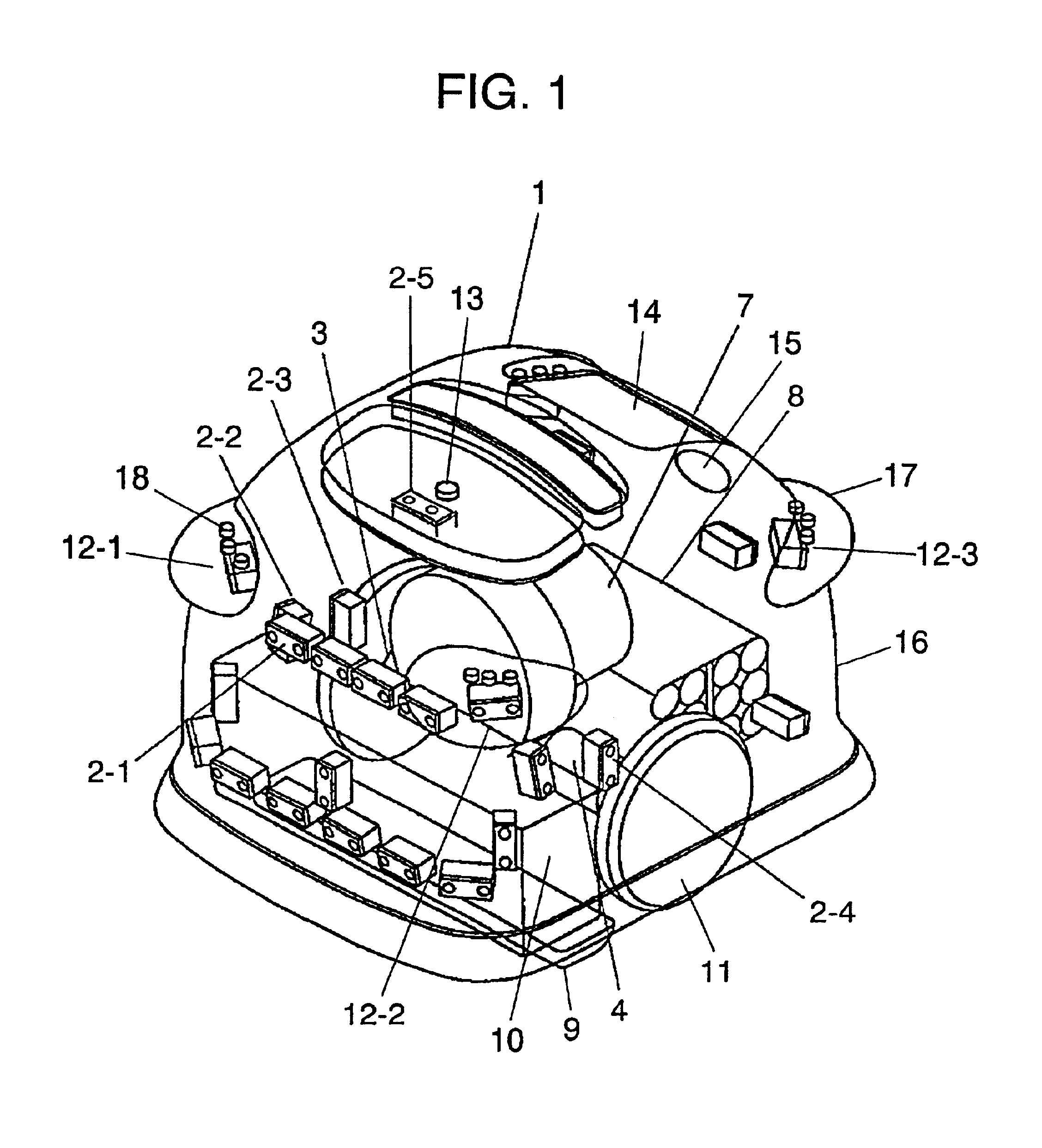
Image

Examples
second embodiment
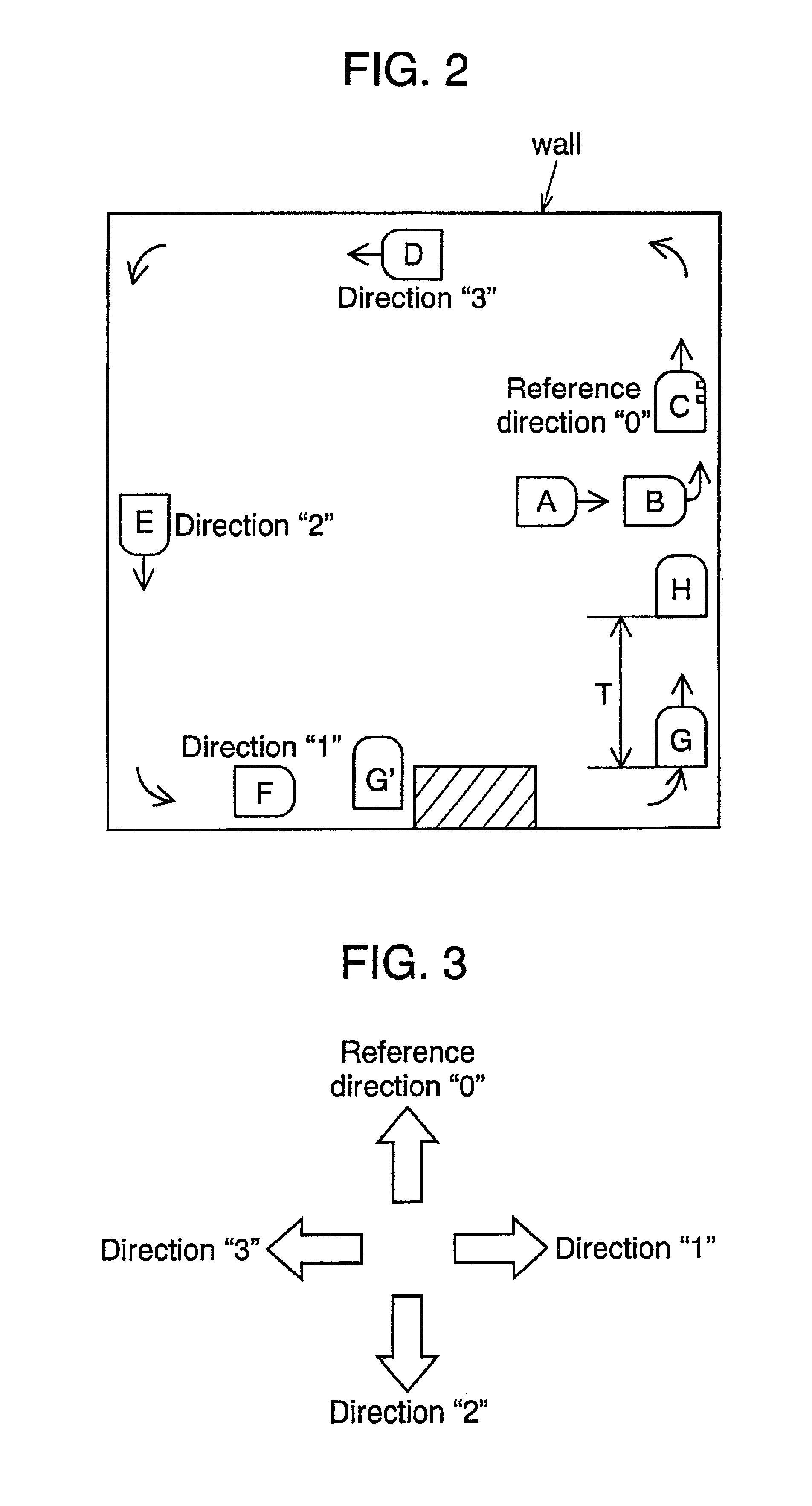
[0026]Described next is a second exemplary embodiment of this invention referring to FIG. 2 and FIG. 5. Like reference numerals are used to designate like structural components as those of the first exemplary embodiment, and their details are omitted. The cleaner of the second embodiment first travels alongside walls. The cleaner then travels in an inner area of a room while moving back and forth in a predetermined direction and another direction opposite the predetermined direction by using direction sensor 5, after determination that the cleaner has completed a full round along the walls of the room. The cleaner can travel and clean dust throughout the room, as it collects the dust in corners of the room while travelling alongside of the walls, and suctions the dust inside of the room while travelling in the inner area with guide of the direction sensor 5.
third embodiment
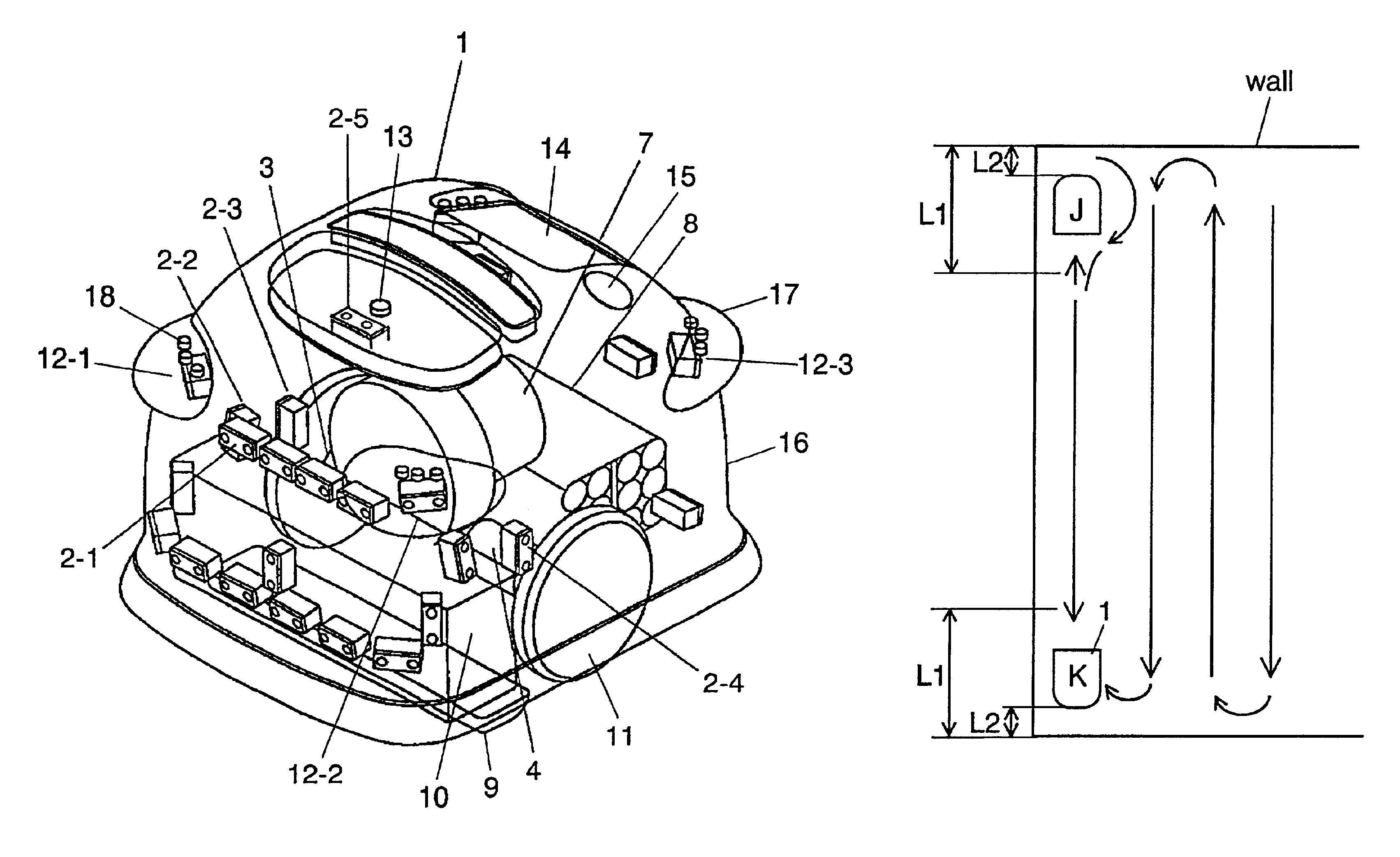
[0027]A third exemplary embodiment of this invention is described next with reference to FIG. 6 and FIG. 7. Again, like reference numerals are used to designate like structural components as those of the first exemplary embodiment, and their details are omitted. The cleaner of the third embodiment first travels alongside walls of a room, and thereafter it travels in an inner area as guided by direction sensor 5. The cleaner again travels alongside the walls, moves toward the inner area of room at point “H” after determination that it has completed a full round along the walls of the room, and turns off electric blower 7 and drive motors 3 and 4 to stop travel at point “I”. There is a case that a door cannot be opened as main body 1 obstructs opening and closing of the door, if the main body 1 stops travelling near a wall as shown in FIG. 7 where there is the door that opens inside the room. A problem of this kind is avoided, however, by causing the main body 1 to stop travelling onl...
fourth embodiment
[0030]Referring to FIG. 8, a fourth exemplary embodiment of the invention is described next. Like reference numerals are used to designate like structural components as those of the first exemplary embodiment, and their details are omitted. When the cleaner of the fourth embodiment travels alongside walls by controlling right drive motor 3 and left drive motor 4 using an output of distance sensor 2-2 mounted to its right side, rotational speeds of the right drive motor 3 and the left drive motor 4 are reduced in a manner to decelerate the travelling speed, when a distance to a detected wall obtained from an output of distance sensor 2-1 mounted to the forward section of the main body is smaller than the first prescribed value L1. In addition, the right drive motor 3 is controlled to be driven into forward rotation and the left drive motor 4 is controlled to be driven into reverse rotation in a manner to make a counterclockwise turn, when a distance to the detected wall obtained from...
PUM
 Abstract
Description
Claims
Application Information