

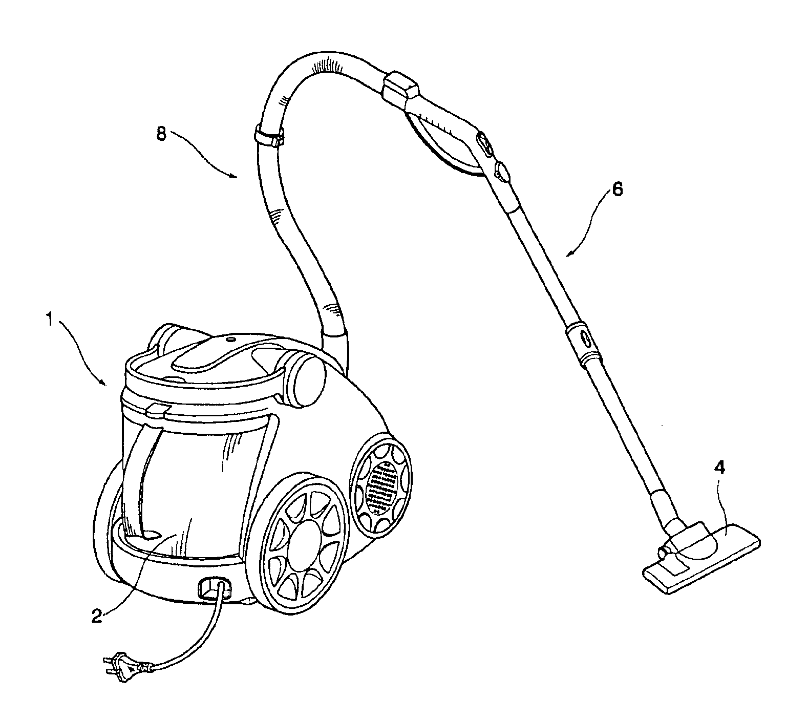
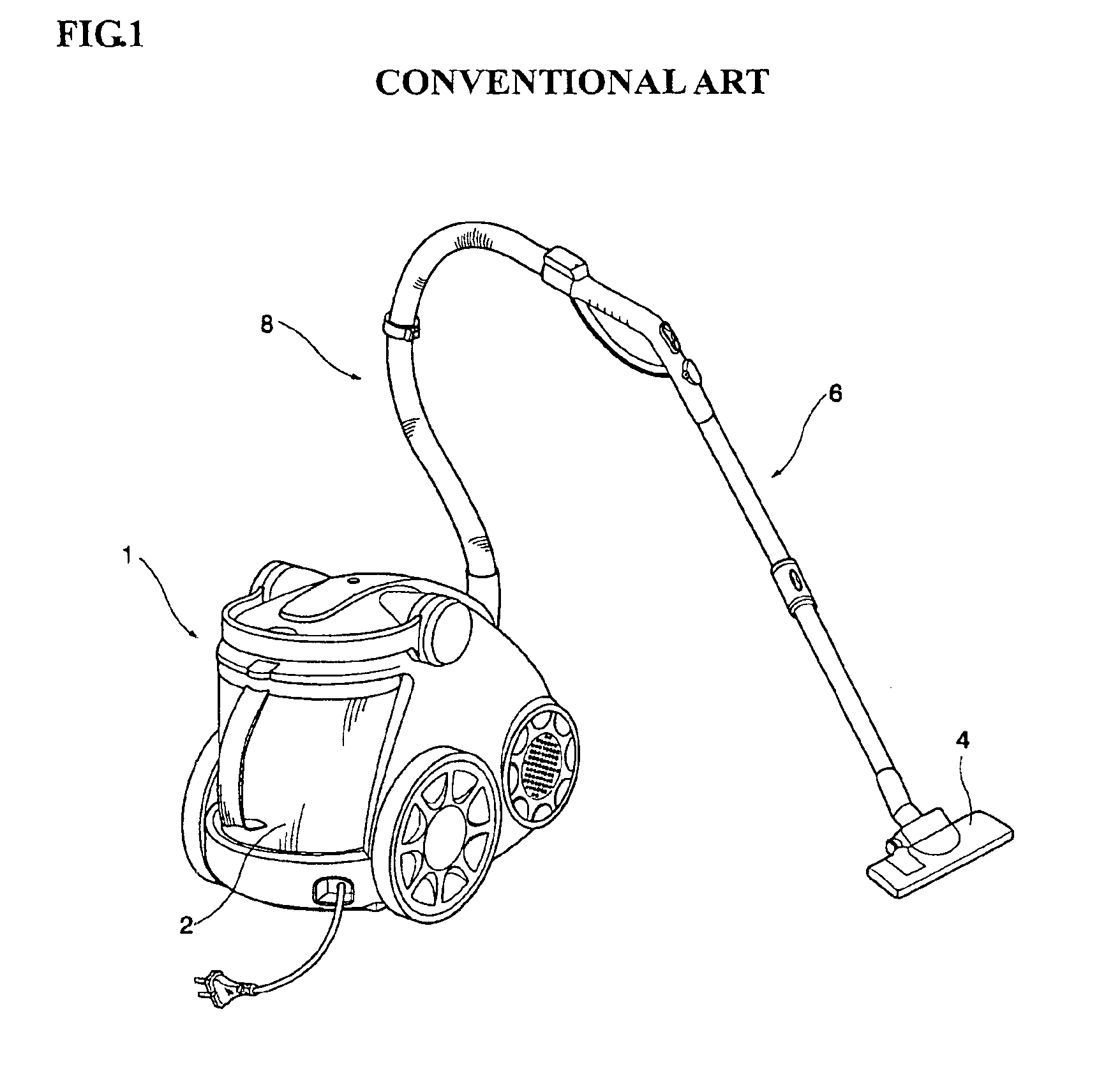
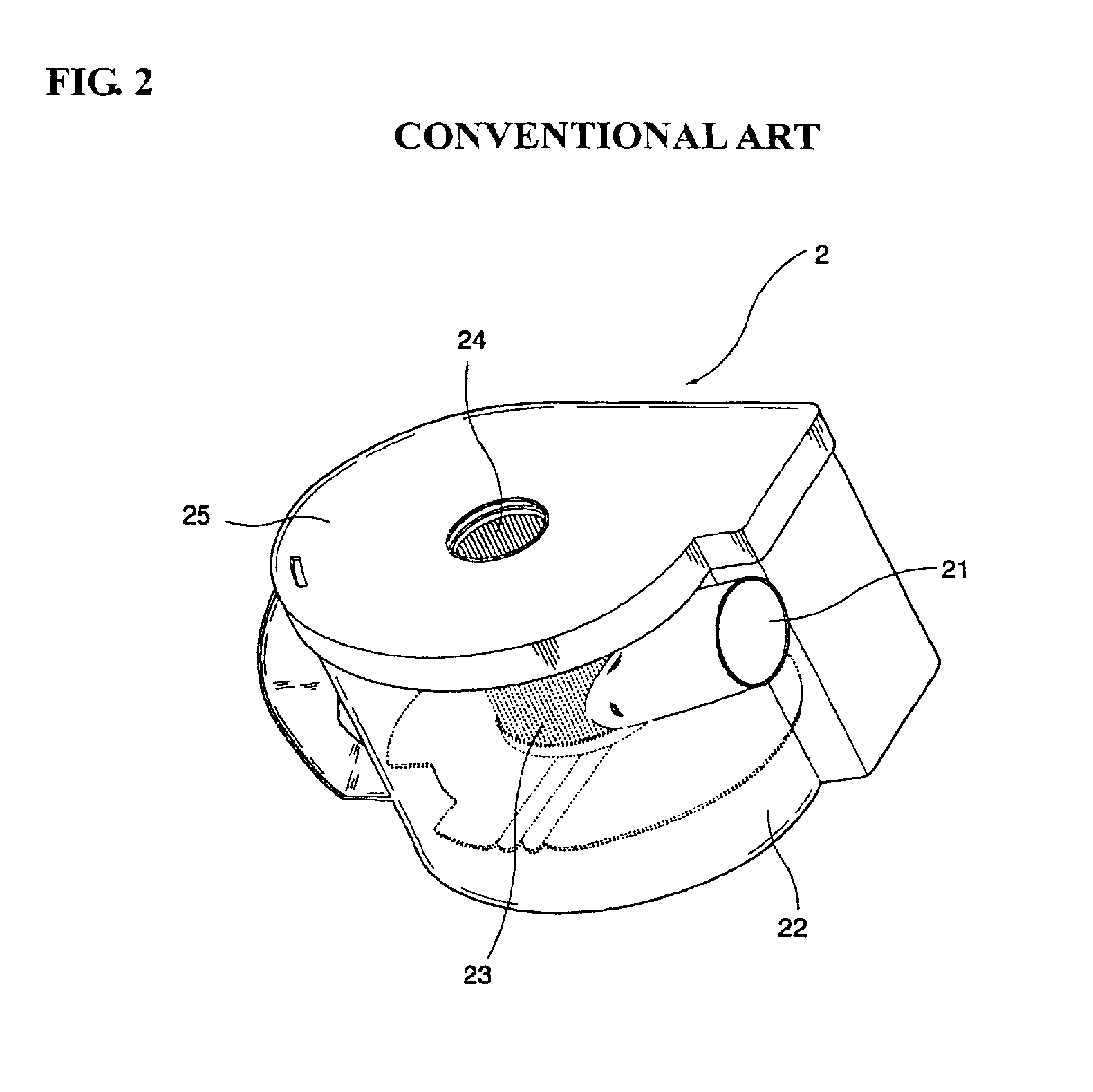
Dust collection unit for use in vacuum cleaner and main body of vacuum cleaner having the same
a technology for vacuum cleaners and dust collection units, which is applied in the direction of cleaning filter means, cleaning equipment, separation processes, etc., can solve the problems of generating suction loss at their respective connecting portions, bringing about material waste, and further lowering the dust collection efficiency of vacuum cleaners
- Summary
- Abstract
- Description
- Claims
- Application Information
AI Technical Summary
Benefits of technology
Problems solved by technology
Method used
Image

Examples
Embodiment Construction
[0026]Hereinafter, preferred embodiments of the present invention will be described in detail with reference to the accompanying drawings.
[0027]FIG. 4A is an exploded perspective view of a dust collection unit 100 according to the present invention, FIG. 4B is an enlarged view of a section of the dust collection unit 100 according to the present invention, and FIG. 6 is a longitudinal sectional view of the dust collection unit 100 according to the present invention. As shown in the figures, the dust collection unit 100 includes a casing 130 of which an upper end is open, and a cover 110 for opening and closing the upper end of the casing.
[0028]The casing 130 defines a predetermined space therein and is formed in a cylindrical shape. As described later, air containing foreign substances, which is sucked into the casing, is the casing 130, is formed into spiral flow, and relatively heavy (large) foreign substances fall downwardly into the casing due to their own weight. An inlet port ...
PUM
| Property | Measurement | Unit |
|---|---|---|
| length | aaaaa | aaaaa |
| circumference | aaaaa | aaaaa |
| diameter | aaaaa | aaaaa |
Abstract
Description
Claims
Application Information