Heat exchangers and fin for heat exchangers and methods for manufacturing the same

Inactive Publication Date: 2005-06-07
SANDEN CORP
View PDF12 Cites 23 Cited by
  • Summary
  • Abstract
  • Description
  • Claims
  • Application Information

AI Technical Summary

Benefits of technology

[0018]Particularly, in the method according to the present invention, in a first processing step, an intermediate pre-formed plate having zigzag strips arranged adjacent to each other is formed by passing a flat plate material between a pair of the first processing rollers. In a following second processing step, the connecting portions of the zigzag strips are successively bent to form a desired structure for a fin according to the present invention, in which the waving strips are connected to each other with the structure defined by the present invention. Therefore, the bending may be performed su

Problems solved by technology

Thus, in a single heat transfer tube, a difference of heat transfer performance occurs in its transverse direction, namely, in the air flow direction, and the overall efficiency of heat transfer of the heat exchanger may be greatly reduced.
Further, because pressing is generally pe

Method used


Image

  • Heat exchangers and fin for heat exchangers and methods for manufacturing the same
  • Heat exchangers and fin for heat exchangers and methods for manufacturing the same
  • Heat exchangers and fin for heat exchangers and methods for manufacturing the same

Examples


Embodiment Construction

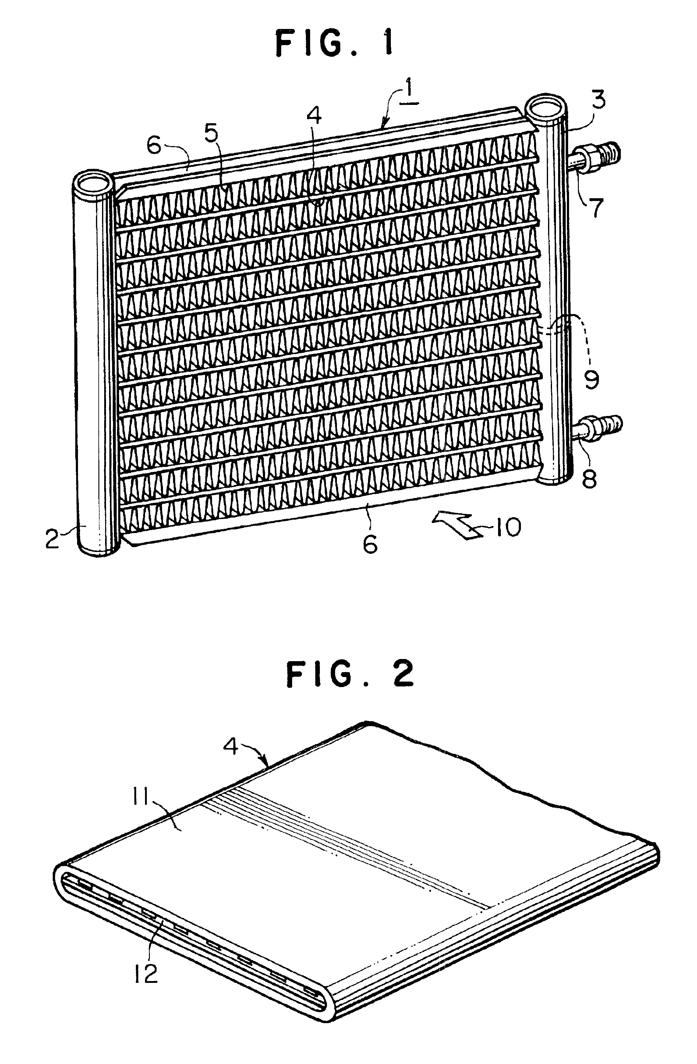
[0035]Referring to FIGS. 1 to 5, a heat exchanger, for example, a condenser, such as a multi-flow type heat exchanger, according to an embodiment of the present invention is disclosed. In FIG. 1, heat exchanger 1 includes a pair of headers 2 and 3 disposed in parallel to each other. A plurality of heat transfer tubes 4 (for example, flat-type refrigerant tubes) are disposed in parallel to each other with a predetermined interval. Tubes 4 fluidly interconnect the pair of headers 2 and 3. Corrugated fins 5 are interposed between the respective adjacent heat transfer tubes 4 and outside of the outermost heat transfer tubes 4 as outermost fins. Side plates 6 are provided on outermost fins 5, respectively.

[0036]Inlet pipe 7 for introducing refrigerant into heat exchanger 1 through header 3 is provided on the upper portion of header 3. Outlet pipe 8 for removing refrigerant from heat exchanger 1 through header 3 is provided on the lower portion of header 3. The inside of header 3 is divid...


PUM

PropertyMeasurementUnit
Lengthaaaaaaaaaa

Abstract

A method for manufacturing a fin for a heat exchanger includes the steps of forming an intermediate pre-formed plate, which has adjacent zigzag strips, by passing a flat plate material between a pair of first processing rollers, and forming a fin by passing the intermediate pre-formed plate between a pair of second processing rollers to bend the zigzag strips at a portion connecting adjacent zigzag strips. The fin includes a plurality of waving strips arranged adjacent to each other in the transverse direction, which are offset in the longitudinal direction. The adjacent waving strips are connected only between the flat portions of the waving strips at a connection length less than or equal to a plate thickness. The fin may be manufactured readily and inexpensively. A heat exchanger using the fin as an inner or outer fin may exhibit superior performance.

Description

BACKGROUND OF THE INVENTION[0001]1. Field of the Invention[0002]The present invention relates to heat exchangers and fins for heat exchangers and methods for manufacturing the fins. More specifically, the invention relates to methods for easily processing fins for heat exchangers, in a form having an excellent brazing ability, and fins manufactured by these methods, and heat exchangers using such fins. Such fins may improve the performance of the heat exchangers by increasing the efficiency of heat transfer.[0003]2. Description of Related Art[0004]In a heat exchanger, it is known that the performance of the heat exchanger may be improved by increasing the efficiency of heat transfer by providing a fin. For example, there are methods for proving inner fins in heat transfer tubes, and methods for providing fins at positions outside of the heat transfer tubes. For instance, an outer fin may be provided at a position between adjacent tubes.[0005]In an inner fin provided in a heat transf...

Claims


Application Information

Patent Timeline
IPC IPC(8): B21D31/04B21D31/00B21D53/04B21D53/02F28F3/00F28F3/02F28F1/40
CPCB21D31/046F28F3/027B21D53/04
Inventor YAMAGUCHI, TORUHOSOYA, KAZUKI
Owner SANDEN CORP
Why Eureka
Try Eureka