
Adjuster for a vehicle seat

a technology for vehicle seats and adjusters, which is applied in the direction of chairs, movable seats, dismountable/non-movable seats, etc., to achieve the effects of simplifying production, reducing the number of mutual spring loads, and simplifying the movement of components

Inactive Publication Date: 2005-06-07
ADIENT LUXEMBOURG HLDG SARL
View PDF40 Cites 20 Cited by
  • Summary
  • Abstract
  • Description
  • Claims
  • Application Information

AI Technical Summary

Benefits of technology

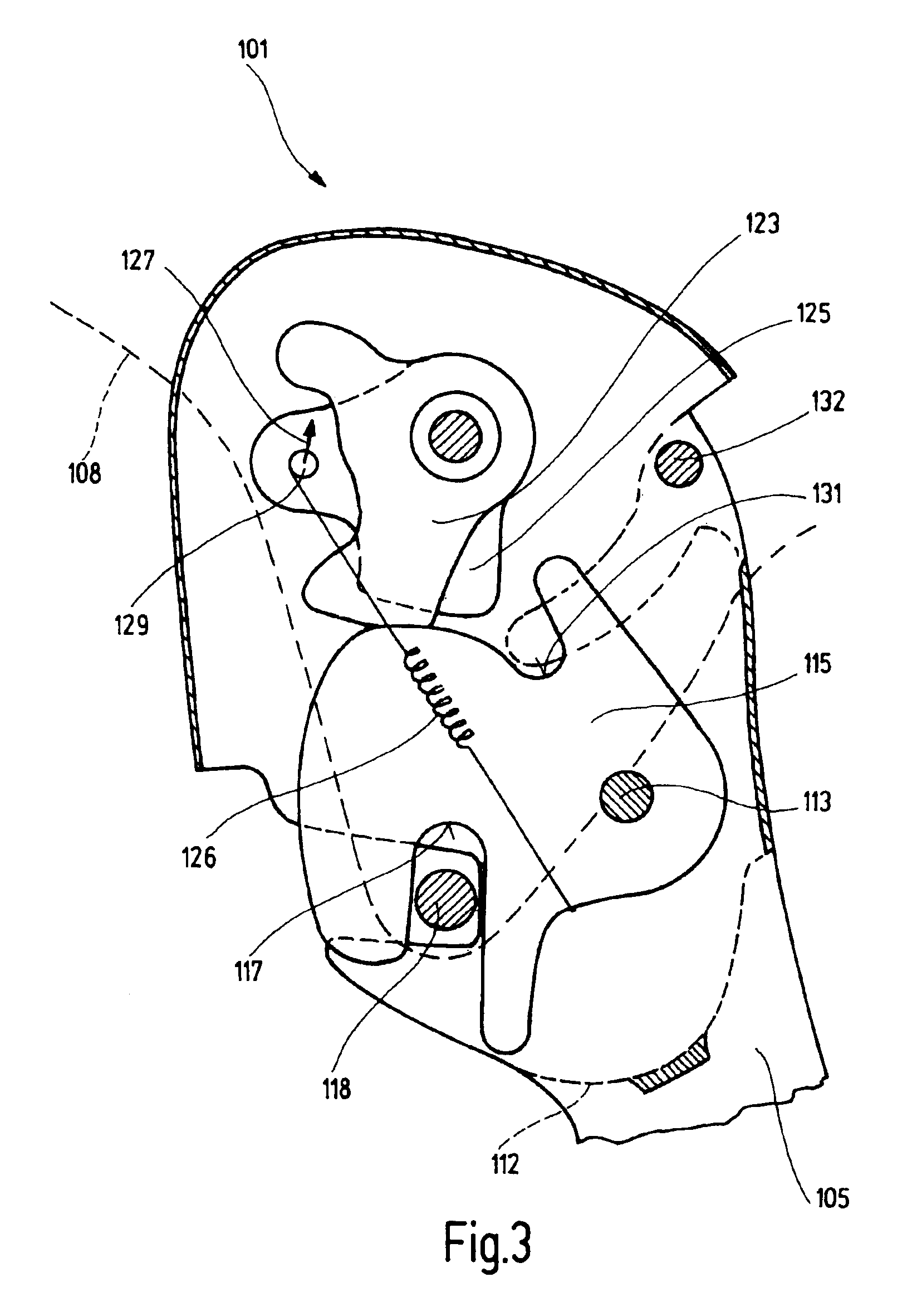
[0005]By virtue of the fact that a pawl is pivotably borne on the first adjuster part and interacts with at least one single locking element of the second adjuster part, in order to lock the adjuster, a simple locking device is provided. By virtue of the fact that the pawl locks the adjuster both in the use and non-use position, one single locking device can be used for the adjuster. In this way, the number of components and, consequently, the production costs, are reduced. These advantages become even clearer when the pawl falls into the same locking position both in the use position and the non-use position, and is preferably also secured by the same securing elements and / or unlocked by the same activation element, this feature also simplifying and improving operation.
[0007]Preferably, there are a corresponding number of locking elements for the different possible positions of the vehicle seat, such as bolts, each interacting with the same pawl, the latter preferably having one or several mouths depending on the arrangement and geometry of the components. The mouths then clutch at least one of the locking elements. Preferably, the mouths, with reference to the pivoting movement of the pawl, are open in the same direction. The mouths are preferably arranged on different sides of the pawl so as to simplify the movements of the components. The mouths can also be replaced by hooks, tongues, or similar elements. The locking elements have been conceived as single elements and not as separate parts of a long-stretched toothed element or similar element. Preferably, the locking elements can move the pawl into its locking position, this feature reducing the number of mutual spring loads and thus simplifying production.

Problems solved by technology

In practice, desires remain, for example with respect to the number of components and therefore production costs.

Method used


Image

  • Adjuster for a vehicle seat
  • Adjuster for a vehicle seat
  • Adjuster for a vehicle seat

Examples


Embodiment Construction

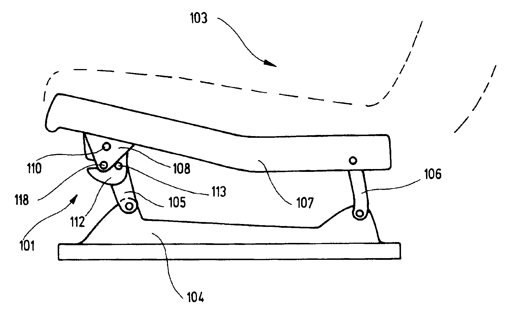
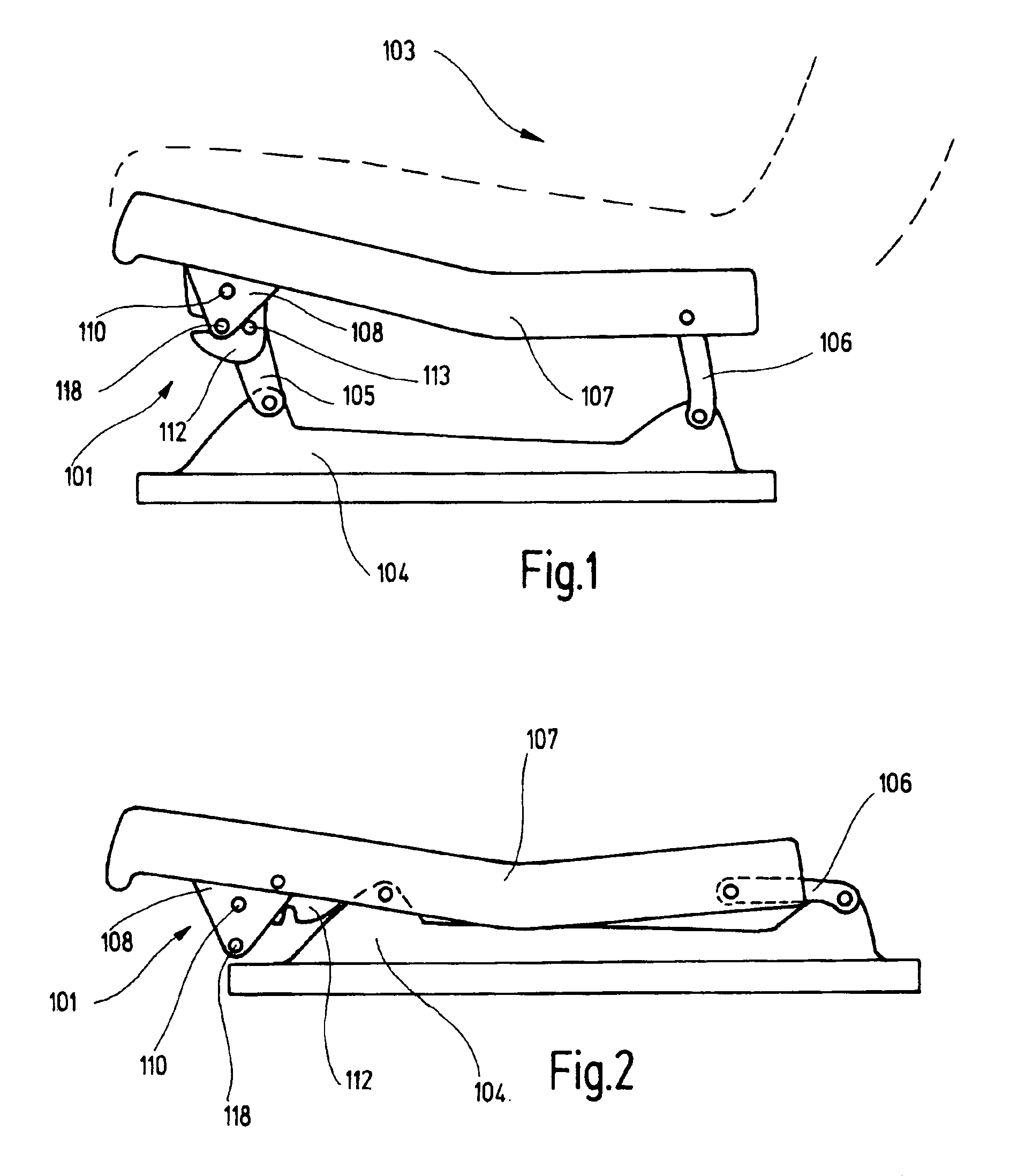
[0016]In the first exemplary embodiment, an adjuster 101 is provided as a seat support of a vehicle seat 103 in a rear seat row of a motor vehicle, for example a van. The adjuster 101 has, with respect to the direction of travel, on each side of the vehicle seat 103, a foot area 104 connected with the vehicle frame, and a front leg 105 pivotably mounted in the front of the foot area 104, as a first adjuster part. The adjuster 101 further includes, with respect to the direction of travel, on each side of the vehicle seat 103, a rear leg 106 pivotably mounted in the rear of the foot area 104, a link 107, pivotably mounted with its rear end on the rear leg 106, and an adaption part 108 fixedly attached to the front end of the link 107 and pointing downward, as a second adjuster part which is pivotably mounted on the front leg 105 by way of an adjuster bolt 110. The two links 107 are connected with one another to form a seat frame bearing the seat pan receiving the seat upholstery.

[0017...


PUM


Abstract

In an adjuster (101) for a vehicle seat, particularly an automobile seat, having a first adjuster part (105) and a second adjuster part (108) which are pivotable relative to one another, thus allowing the vehicle seat to pivot between at least one use position and one non-use position, a pawl (115) pivotably borne on the first adjuster part (105) interacts with at least one single locking element (118, 132) of the second adjuster part (108) to lock the adjuster (101), wherein the pawl (115) locks the adjuster (101) in the use position as well as in the non-use position.

Description

CROSS-REFERENCE TO RELATED APPLICATION[0001]This application is a continuation of International Application No. PCT / EP02 / 12926, which was filed Nov. 19, 2002, and is entirely incorporated herein by reference.BACKGROUND OF THE INVENTION[0002]The present invention pertains to an adjuster for a vehicle seat, in particular for a motor vehicle seat, having a first adjuster part and a second adjuster part which are pivotable relative to one another and by way of which the vehicle seat can be pivoted between at least one use position and at least one non-use position.[0003]In a known adjuster of this type, used for adjusting the height or passing into a level floor position, the use position and non-use position are secured by locking devices. In practice, desires remain, for example with respect to the number of components and therefore production costs.BRIEF SUMMARY OF THE INVENTION[0004]The present invention is based on the object of improving an adjuster, such as an adjuster of the typ...

Claims


Application Information

Patent Timeline
Patent Type & Authority Patents(United States)
IPC IPC(8): B60N2/02B60N2/30B60N2/20B60N2/16A47C7/00B60N2/36
CPCB60N2/1615B60N2/1685B60N2/169B60N2/309B60N2/30B60N2/3065B60N2/206
Inventor PETRY, MARKUS
Owner ADIENT LUXEMBOURG HLDG SARL
Learn More