
Vacuum pump with pump rotor pairs and permanent magnet motor

a permanent magnet motor and vacuum pump technology, applied in the field of vacuum pumps, can solve the problems of reducing efficiency, vacuum pump being more susceptible to mechanical loss, and failure to make vacuum pump compact, and achieve the effect of reducing heat generation and high reliability

Inactive Publication Date: 2005-06-07
EBARA CORP
View PDF16 Cites 17 Cited by
  • Summary
  • Abstract
  • Description
  • Claims
  • Application Information

AI Technical Summary

Benefits of technology

[0011]The present invention has been made in view of the foregoing circumstances. It is therefore an object of the present invention to provide a vacuum pump which is capable of highly reliable operation using a motor having a motor rotor whose heat generation is minimized and having capability of operating safely under high-temperature conditions.

Problems solved by technology

In the case where the motor is disposed at the outlet port side heated by the compressed gas and with the motor M itself generating heat, the motor M tends to be excessively heated to a high temperature and hence greatly reduced in efficiency.
The motor M having such a structure causes the vacuum pump to be more susceptible to a mechanical loss, and also fails to make the vacuum pump compact.
However, if the vacuum pump draws in a corrosive gas used in the semiconductor fabrication process, the permanent magnets of the motor are corroded by the gas.
Consequently, the permanent magnets reduce their magnetic forces and are damaged, possibly resulting in a motor failure.
If some of permanent magnets are damaged while the motor is being assembled, then the permanent magnets tend break and scatter while the motor is in rotation, thus causing the vacuum pump to stop.
Consequently, the permanent magnets detach from the motor rotor during rotation, resulting in a breakdown of the motor.
The shaft seal mechanism makes it difficult to simplify the structure of the vacuum pump, and also makes it difficult to make the vacuum pump compact.
These problems occur also in other positive-displacement vacuum pumps such as a screw vacuum pump.

Method used


Image

  • Vacuum pump with pump rotor pairs and permanent magnet motor
  • Vacuum pump with pump rotor pairs and permanent magnet motor
  • Vacuum pump with pump rotor pairs and permanent magnet motor

Examples


first embodiment

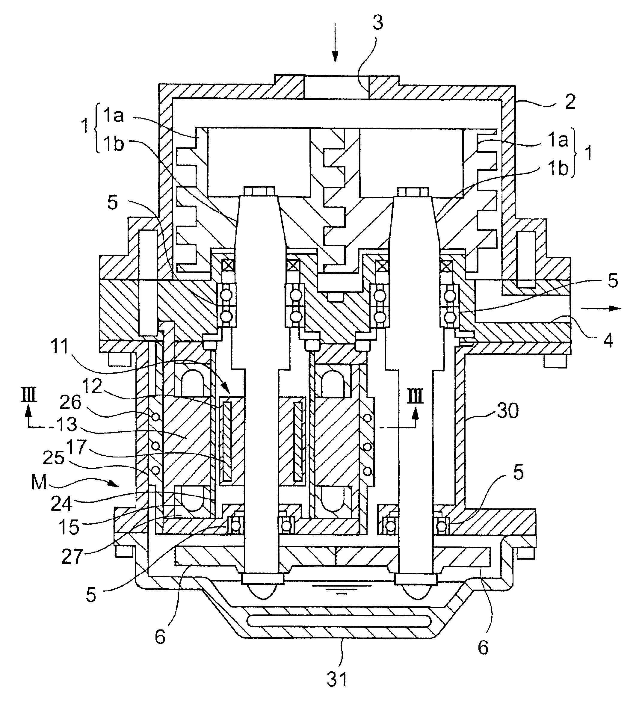
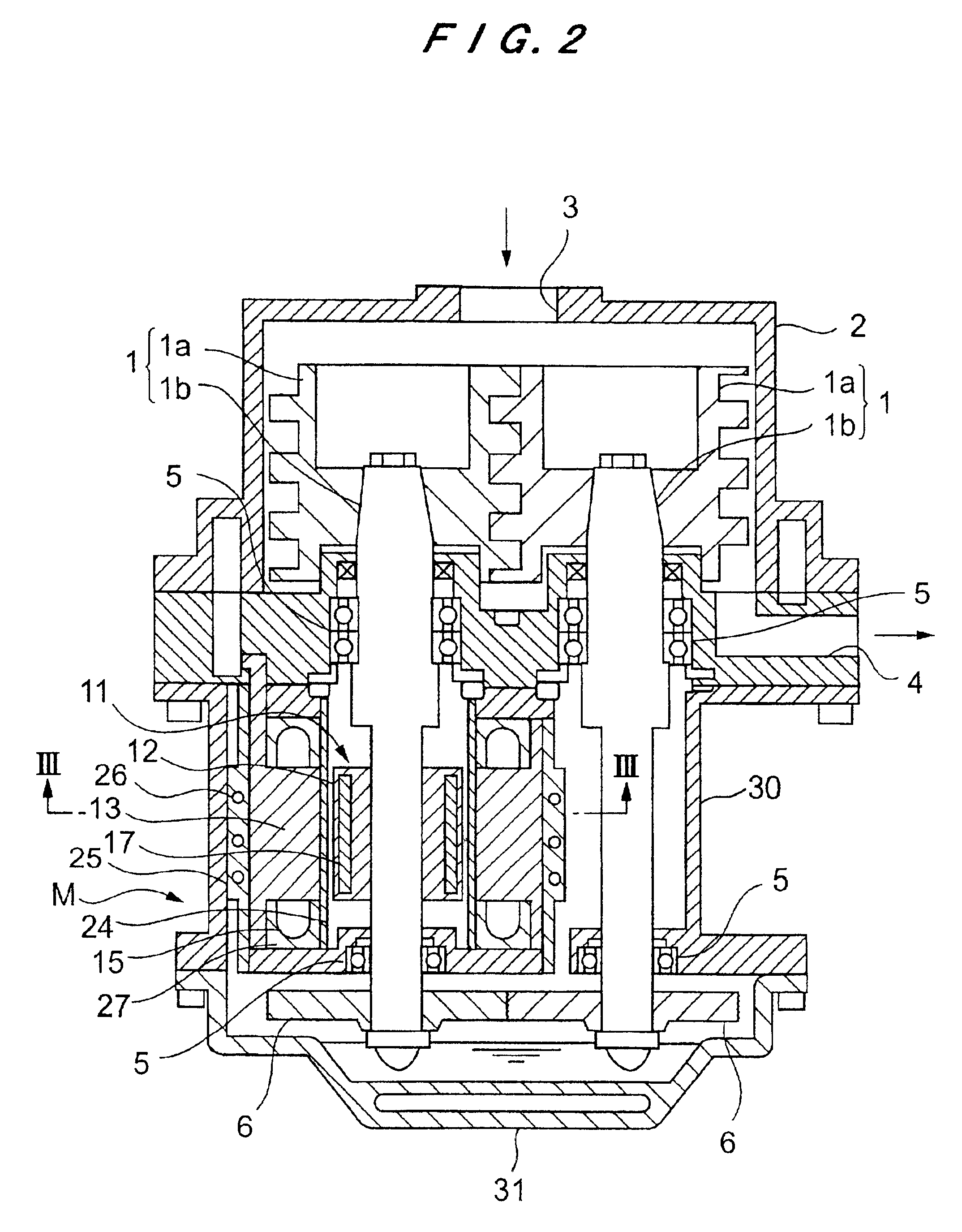
[0034]A positive-displacement screw vacuum pump according to the present invention will be described below with reference to FIGS. 2 to 4A through 4D.

[0035]As shown in FIG. 2, the positive-displacement screw vacuum pump has a pair of pump rotors 1 each comprising a rotor 1a and a main shaft 1b supporting the rotor 1a. A pair of confronting rotors 1a are disposed in a casing 2. The positive-displacement screw vacuum pump is vertically installed such that an axis of the pump rotor extends vertically, timing gears are placed at a lower part, and an inlet port is placed at an upper part. The casing 2 has an inlet port 3 defined in an upper wall thereof and an outlet port 4 defined in a lower wall thereof. The pair of the pump rotors 1 are rotatably supported by bearings 5 to allow the rotors 1a to rotate within the casing 2 with a slight clearance kept between the confronting rotors 1a and between each of the rotors 1a and the casing 2. The bearings 5 are not disposed at the side of the...

second embodiment

[0052]A positive-displacement multistage Roots vacuum pump according to the present invention will be described below with reference to FIGS. 5 and 6.

[0053]As shown in FIG. 5, the positive-displacement multistage Roots vacuum pump according to the second embodiment has a pair of confronting pump rotors 31 each comprising rotors 31a, 31b and 31c and a main shaft 31d. The rotors 31a, 31b and 31c having different axial widths from each other are spaced at substantially equal intervals and mounted on the main shafts 31d. The pair of the confronting pump rotors 31 are supported by bearings 33, respectively, and their rotors 31a, 31b and 31c are housed in a casing 32. The vacuum pump has an inlet port 34 disposed above the rotor 31a which has the largest width, and also has an outlet port 35 disposed below the rotor 31c which has the smallest width.

[0054]In FIG. 6, a small clearance is formed between the confronting rotors 31b and between the rotors 31b and the casing 32 to allow the roto...


PUM


Abstract

A vacuum pump has a casing having an inlet port and an outlet port, and a pair of confronting pump rotors which are provided inside the casing and synchronously rotatable for drawing in a gas from the inlet port and discharging the gas from the outlet port. A motor for rotating the confronting pump rotors is a permanent magnet motor having a stator and a motor rotor. The motor rotor has an iron core and permanent magnets disposed within the iron core.

Description

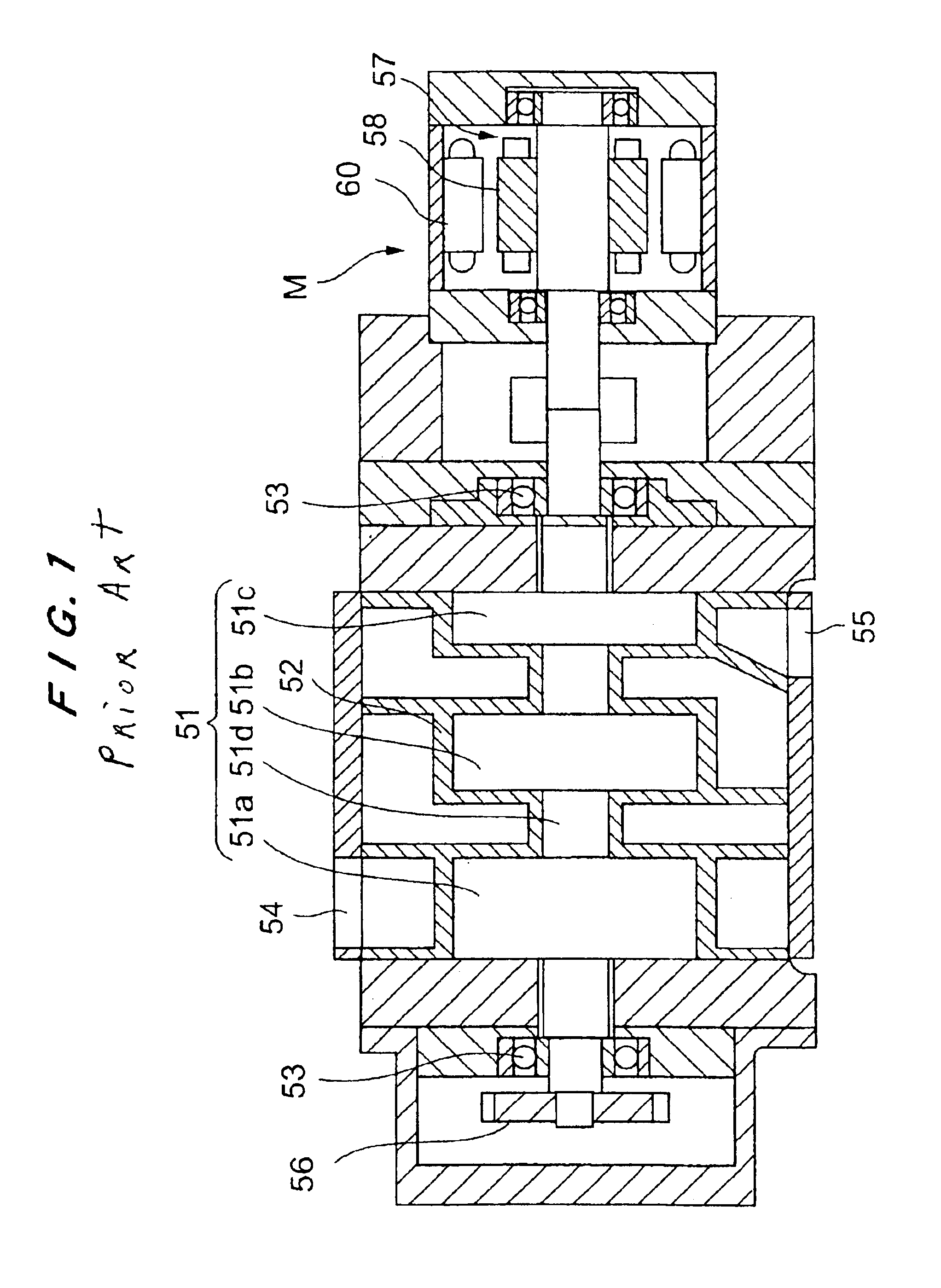
BACKGROUND OF THE INVENTION[0001]1. Field of the Invention[0002]The present invention relates to a vacuum pump, and more particularly to a vacuum pump which is preferably used for evacuating a gas from a vacuum chamber used in a semiconductor fabrication process.[0003]2. Description of the Related Art[0004]There has heretofore been known a vacuum pump called a positive-displacement pump having a pair of pump rotors which rotate synchronously with each other for drawing in and discharging a gas. The positive-displacement vacuum pumps include Roots vacuum pumps, screw vacuum pumps, and the like, and are widely used for evacuating a process gas from a vacuum chamber used in a semiconductor fabrication process.[0005]FIG. 1 of the accompanying drawings is a cross-sectional view showing a conventional Roots-type positive-displacement vacuum pump which comprises a multistage Roots vacuum pump having a pair of pump rotors housed in a casing. Each of the pump rotors has three-stage Roots rot...

Claims


Application Information

Patent Timeline
IPC IPC(8): H02K1/27F04B35/00F04B37/16F04B39/00F04C18/16F04C18/18F04C23/02F04C25/02F04C29/00H02K1/14H02K1/16H02K1/22H02K7/14H02K15/03H02K21/16
CPCH02K1/276F04B35/00
Inventor OJIMA, YOSHINORIMATAKE, KOZOINADA, TAKANORIYANAGISAWA, KIYOSHI
Owner EBARA CORP
Learn More