High-frequency heating apparatus with illumination device

a technology of illumination device and heating apparatus, which is applied in the direction of domestic cooling apparatus, furnaces or ranges, and stoves or ranges. it can solve the problems of steam that goes back from the heating chamber b, vibration is transmitted, and disconnection, so as to improve the insulation performance, and improve the insulation performan

Inactive Publication Date: 2005-06-07
PANASONIC CORP
View PDF4 Cites 2 Cited by
  • Summary
  • Abstract
  • Description
  • Claims
  • Application Information

AI Technical Summary

Benefits of technology

[0009]With the above configuration, the illumination device is held by the nails of the air guide with slight play. Since the peripheral portion of the illumination device is in contact with the waveguide, the illumination device is prevented from disengaging from the nails. The illumination device can thus be fixed without using a vis. Further, the guides that are provided in the central plate and the bottom plate of the air guide can guide water droplets so that they do not drop onto electric parts that are disposed under the air guide.
[0011]According to the invention, the air guide is made of a metal plate material and has a top plate that is provided with at least two inverted-L-shaped nails, and one nail is inserted in a hole of the illumination device and another nail holds a peripheral portion of the illumination device. With this configuration, the illumination device is held with slight play, which prevents the problem that when the door of the radio-frequency heating apparatus is opened or closed, vibration is transmitted to the filament or the like and a disconnection may occur there.
[0012]According to the invention, the illumination device is attached at such a position that one peripheral portion thereof comes close to an end of the air guide, and when the air guide is attached to the radio-frequency wave generating device the peripheral portion of the illumination device contacts the waveguide. This prevents the illumination device from disengaging from the nails of the air guide.
[0013]According to the invention, the air guide has a central plate that is provided with a projected surface that is inclined so as to decrease in height in a direction from the outside to the heating chamber. With this configuration, when steam goes back from the heating chamber and condenses into dew on the central plate of the air guide and water droplets drop down its inner surface, the water droplets reach the projected surface and are guided by the projected surface to the wall surface of the heating chamber. This prevents the problem that water droplets drop from the air guide onto electric parts to deteriorate their insulation performance. This prevents the problem that water droplets drop from the air guide onto underlying electric parts to deteriorate their insulation performance.
[0014]According to the invention, the air guide has a bottom plate that is provided with an inclined surface that is inclined so as to decrease in height in a direction from the outside to the heating chamber. With this configuration, even if steam goes back from the heating chamber and condenses into dew on the bottom plate of the air guide, water droplets are guided by the inclined surface to the wall surface of the heating chamber. This prevents the problem that water droplets drop from the air guide onto underlying electric parts to deteriorate their insulation performance.

Problems solved by technology

However, fixing the illumination device 8 with a vis causes a problem that when the door 2 of the radio-frequency heating apparatus is opened or closed, vibration is transmitted to the filament or the like and a disconnection may occur there.
This results in a problem that after completion of cooking, steam that goes back from the heating chamber 1 likely condenses into dew, whereby water droplets may drop onto electric parts that are disposed under the air guide 6 to deteriorate their insulation performance.

Method used


Image

  • High-frequency heating apparatus with illumination device
  • High-frequency heating apparatus with illumination device
  • High-frequency heating apparatus with illumination device

Examples


embodiment 1

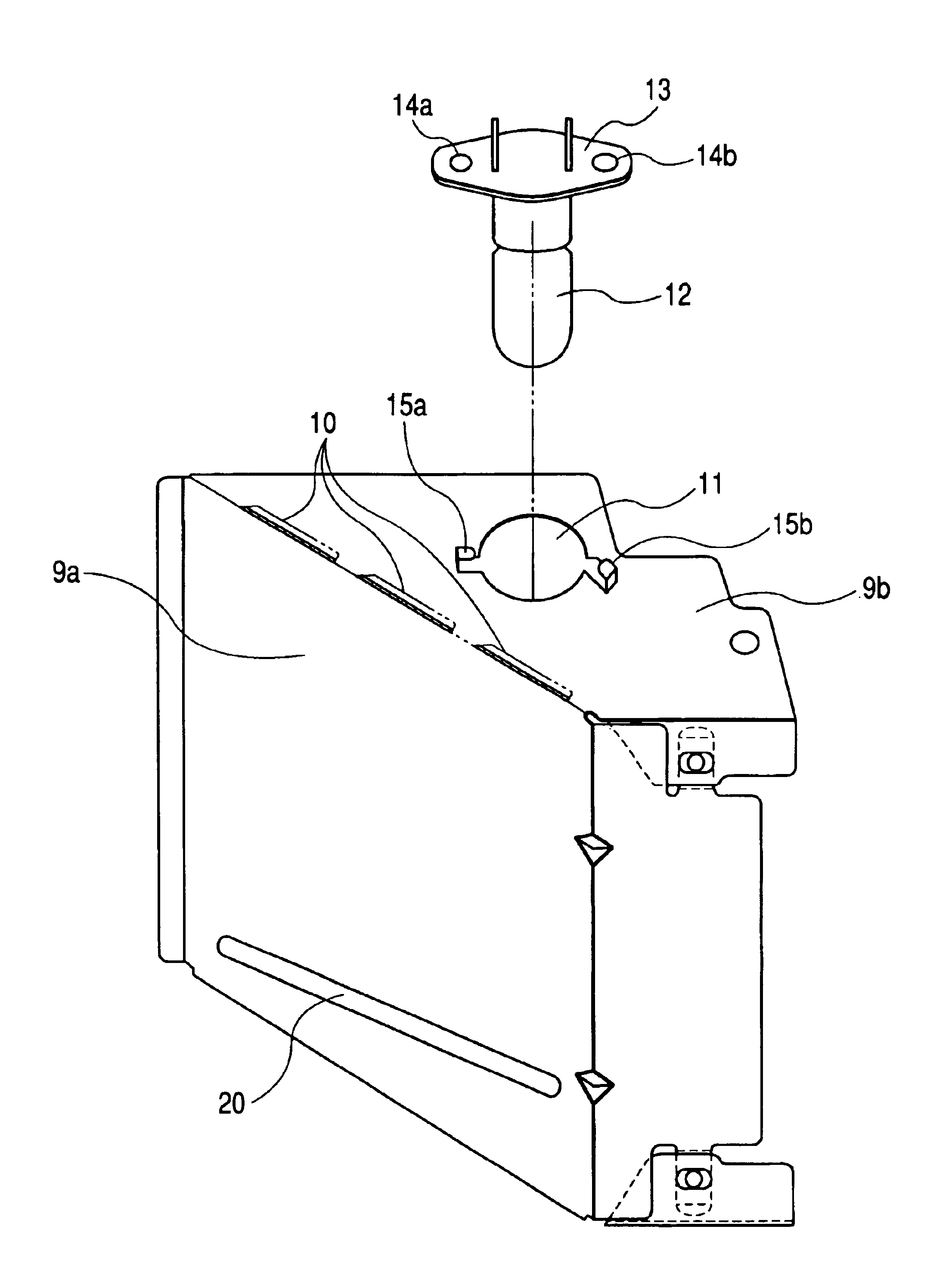
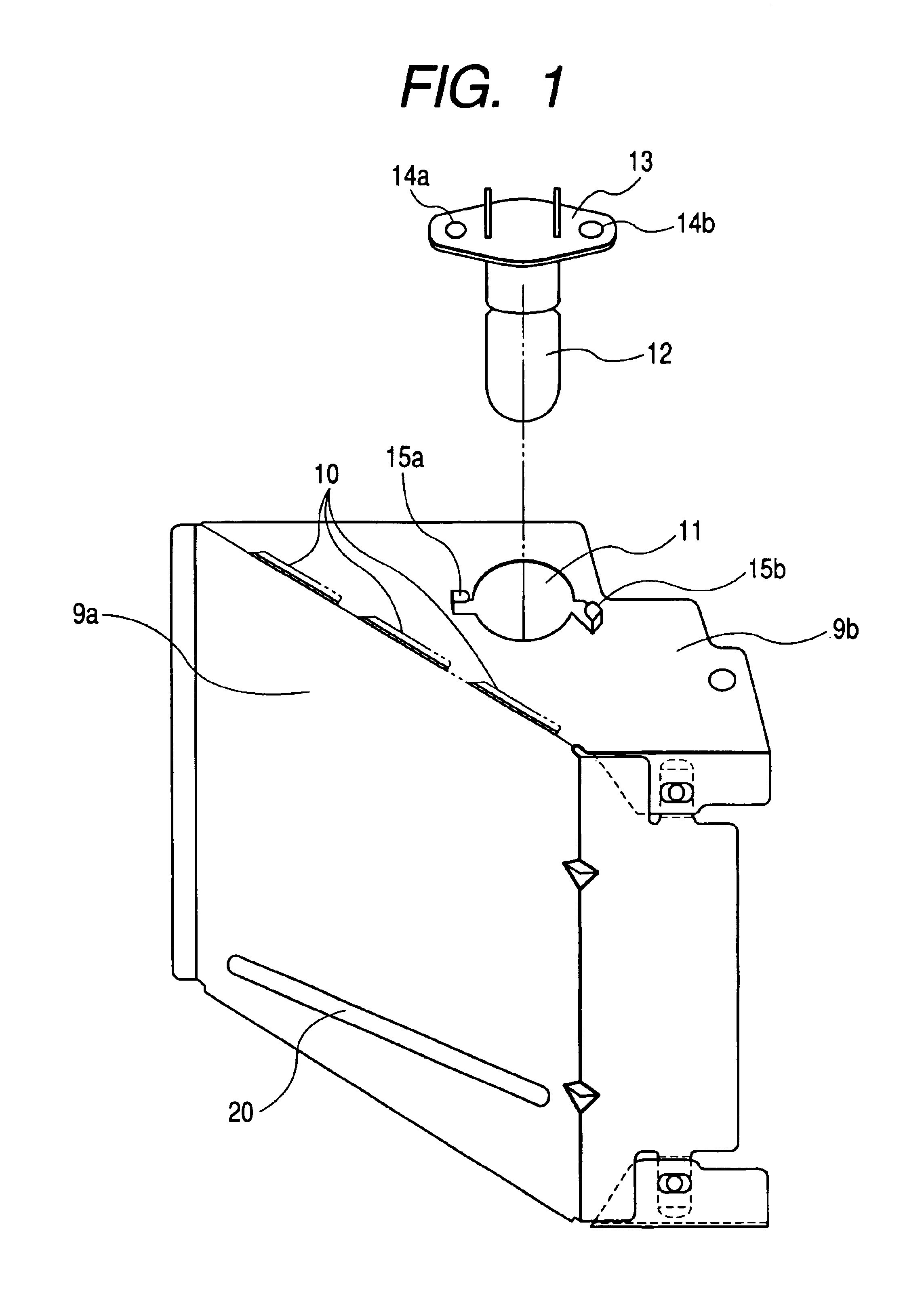
[0021]FIG. 1 shows the appearance of an air guide of a radio-frequency heating apparatus according to a first embodiment of the invention.

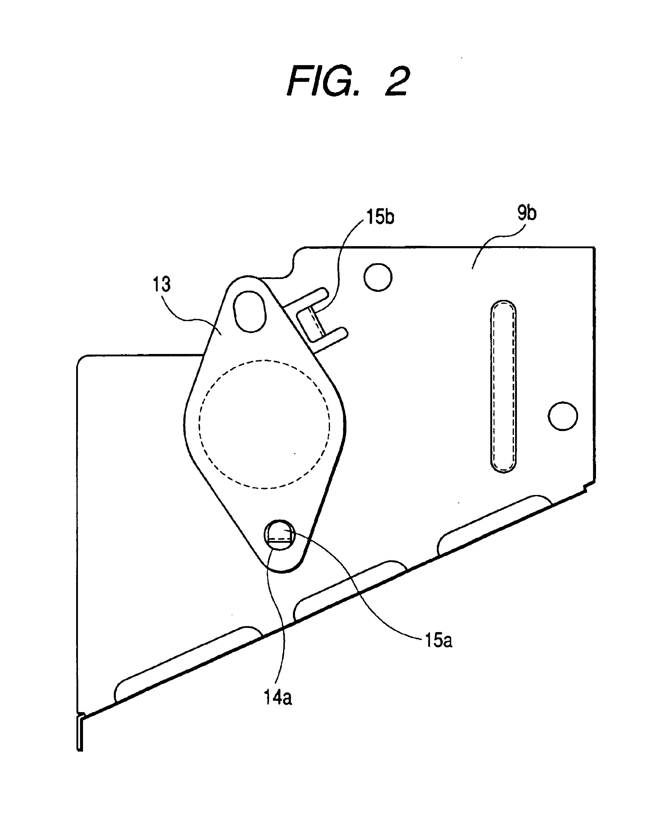
[0022]FIG. 2 shows the air guide as viewed from above when an illumination device is attached to it in the radio-frequency heating apparatus according to the first embodiment of the invention.

[0023]In FIGS. 1 and 2, reference symbols 9a, 9b, and 9c denote a central plate, a top plate, and a bottom plate (not shown) of the air guide, respectively. Slit-like holes 10 are formed at the boundaries between the central plate 9a and the top plate 9b and between the central plate 9a and the bottom plate 9c. The air guide is given a generally U-shaped form by bending the top plate 9b and the bottom plate 9c. The top plate 9b has a lamp hole 11 for fixing a lamp 12 as an illumination device for illuminating a cooking object in the heating chamber. Inverted-L-shaped nails 15a and 15b are provided adjacent to the hole 11. The lamp 12 is provided with a holdin...


PUM


Abstract

To realize an air guide of a radio-frequency heating apparatus that enables fixing of a lamp without use of a vis though it is made of a metal plate material. An air guide 9 made of a metal plate material is formed with two inverted-L-shaped nails 15. A holding portion 13 of a lamp 12 is hooked on the nails 15 and a waveguide holding plate 19 is brought into contact with an opposed surface of the holding portion 13 of the lamp 12. As a result, the lamp 12 can be fixed without using a vis and hence a step of fixing the lamp 12 with a vis can be eliminated. An inexpensive configuration can be realized that is free of fear that a disconnection may occur in a filament due to vibration.

Description

[0001]This application claims the benefit of International Application Number PCT / JP02 / 11800, which was published in English on May 22, 2003.TECHNICAL FIELD[0002]The present invention relates to the structure of an air guide for guiding air to a heating chamber in a radio-frequency heating apparatus.BACKGROUND OF THE ART[0003]Among conventional radio-frequency heating apparatuses of a type concerned are ones that are provided with an air guide for guiding air to a heating chamber to prevent dew condensation there and clouding of a door inner surface. The air guide is produced by shaping a metal plate-like material or a resin material into a generally U-shaped form. An illumination device is fixed to the inside of the air guide. FIG. 5 shows the configuration of a conventional radio-frequency heating apparatus.[0004]In FIG. 5, reference numeral 1 denotes a heating chamber for housing a cooking object; 2, a door for inputting and outputting the cooking object; 3, a magnetron for suppl...

Claims


Application Information

Patent Timeline
Patent Type & Authority Patents(United States)
IPC IPC(8): H05B6/80H05B6/64F24C7/02
CPCH05B6/6444H05B6/642F24C7/02
Inventor KANZAKI, KOUJIKAWAI, KAZUHIRO
Owner PANASONIC CORP
Why Eureka
Try Eureka