Erasing method and apparatus for plasma display panel

Inactive Publication Date: 2005-06-07
LG ELECTRONICS INC
View PDF5 Cites 10 Cited by
  • Summary
  • Abstract
  • Description
  • Claims
  • Application Information

AI Technical Summary

Benefits of technology

[0017]Accordingly, it is an object of the present invention to provide an erasing method and apparatus for a plasma display panel that is capable of minimizing spurious wall charges left after an erasing discharge.
[0033]Said rectangular erasing pulse is applied to the second row electrode in the rising edge of said ramp erasing pulse to thereby raise said ramp erasing pulse into a maximum voltage.

Problems solved by technology

However, the fine-width erasing pulse rect-ers or the ramp erasing waveform ramp-ers applied currently raises a problem in that a discharge characteristic deviation is not considered, or additional wall charges are generated due to a voltage applied after the erasing discharge to be left within the cell.
However, the cells of the PDP have some difference in a discharge delay characteristic because physical and electrical deviations within the cells exist.

Method used


Image

  • Erasing method and apparatus for plasma display panel
  • Erasing method and apparatus for plasma display panel
  • Erasing method and apparatus for plasma display panel

Examples


first embodiment

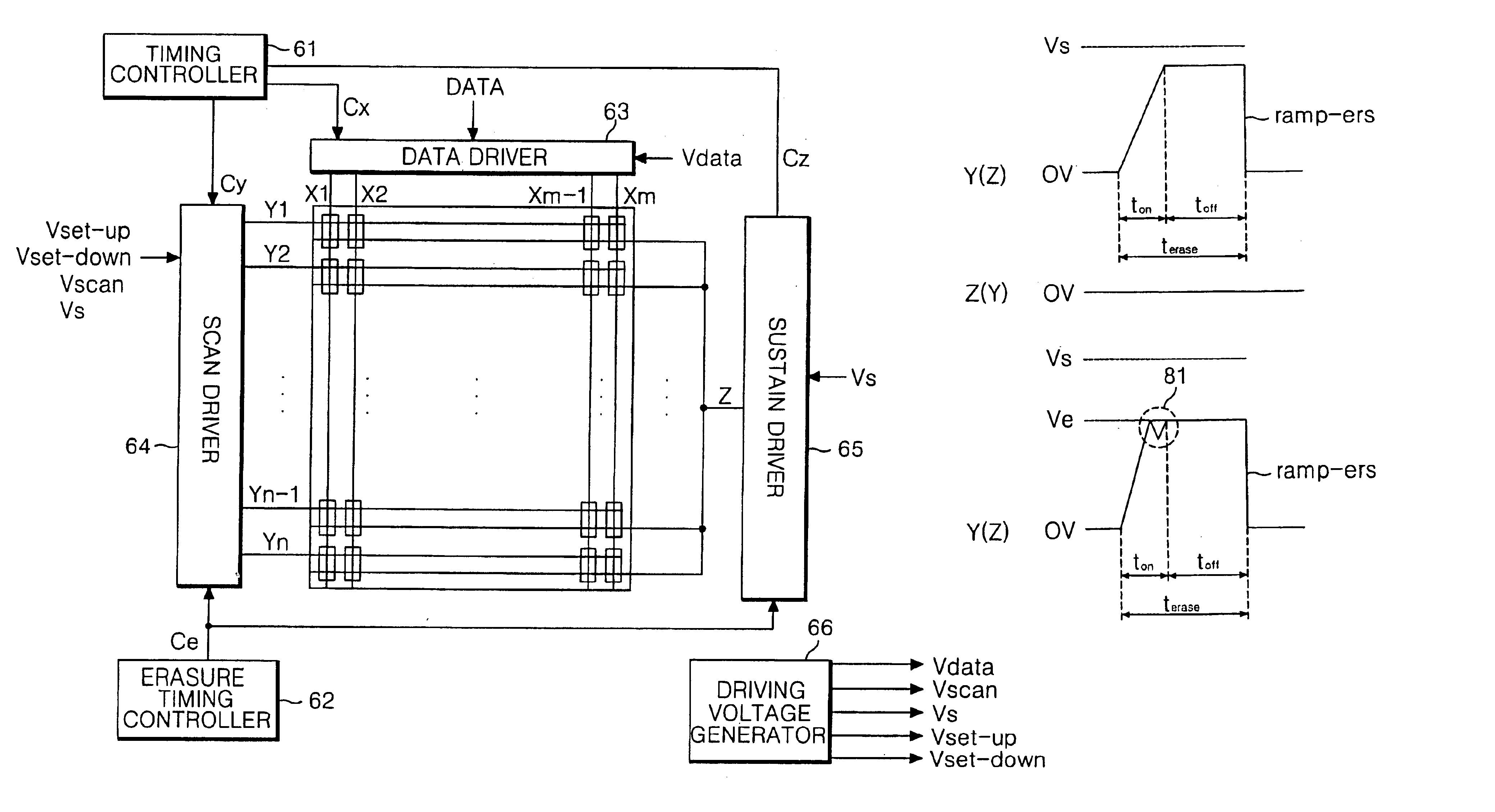
[0045]FIG. 6 shows a driving apparatus for a plasma display panel (PDP) according to the present invention.

[0046]Referring to FIG. 6, the driving apparatus includes a data driver 63 for supplying a data to address electrodes X1 to Xm of the PDP, a scan driver 64 for driving scan electrodes Y1 to Yn of the PDP, a sustain driver 65 for driving a sustain electrode Z which are a common electrode, a timing controller 61 for controlling each of electrode drivers 63 to 65, an erasure timing controller 62 for controlling erasure timing of the scan driver 64 and the sustain driver 65, and a driving voltage generator 66 for generating driving voltages Vdata, Vs, Vset-up and Vset-down.

[0047]The data driver 63 is subject to a reverse gamma correction and an error diffusion, etc. by a reverse gamma correcting circuit and an error diffusing circuit, etc. and then applies data mapped by a sub-field mapping circuit for each sub-field to the address electrodes X1 to Xm simultaneously under control o...

second embodiment

[0059]FIG. 9 is a waveform diagram for explaining a method of driving a plasma display panel according to the present invention.

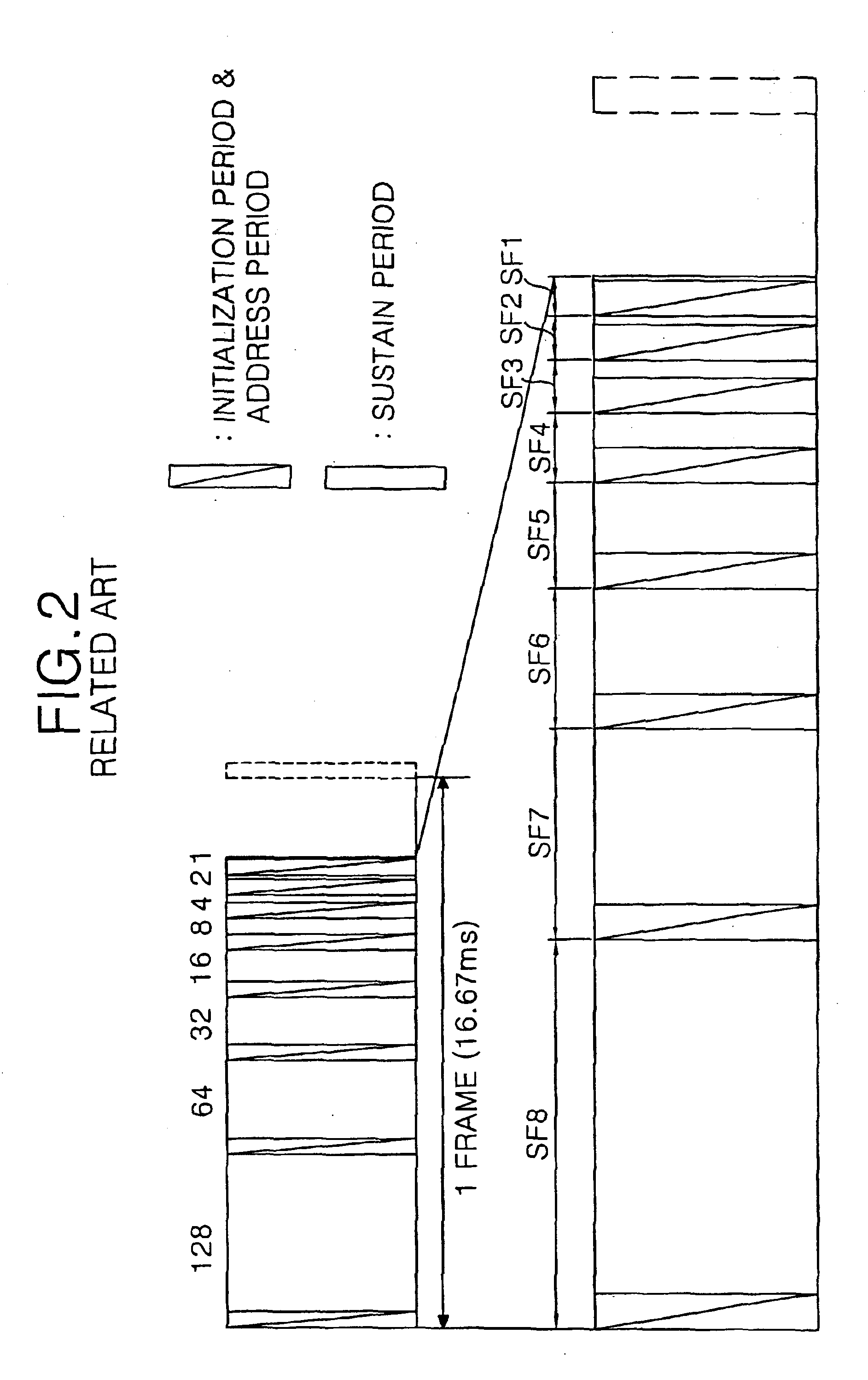
[0060]Referring to FIG. 9, the PDP is divided into an initialization period for initializing the full field, an address period for selecting a cell, a sustain period for sustaining a discharge of the selected cell, and an erasure period for re-binding wall charges and space charges generated in the sustain period for the purpose of making a time divisional driving thereof.

[0061]In the initialization period, a ramp-up pulse Ramp-up is simultaneously applied to all the scan electrodes Y in a set-up interval SU. A discharge is generated within the cells at the full field with the aid of the ramp-up pulse Ramp-up. By this set-up discharge, positive wall charges are accumulated onto the address electrode X and the sustain electrode Z while negative wall charges are accumulated onto the scan electrode Y. In a set-down interval SD, a ramp-down pulse Ramp-down fall...


PUM


Abstract

An erasing method and apparatus for a plasma display panel that is capable of minimizing spurious wall charges left after an erasing discharge. In the erasing method, an erasing signal taking a ramp waveform shape is applied to any one of first and second electrodes for alternately causing a sustain discharge. A voltage of said erasing signal is sustained at a voltage upon erasing discharge after the erasing discharge caused by said erasing signal.

Description

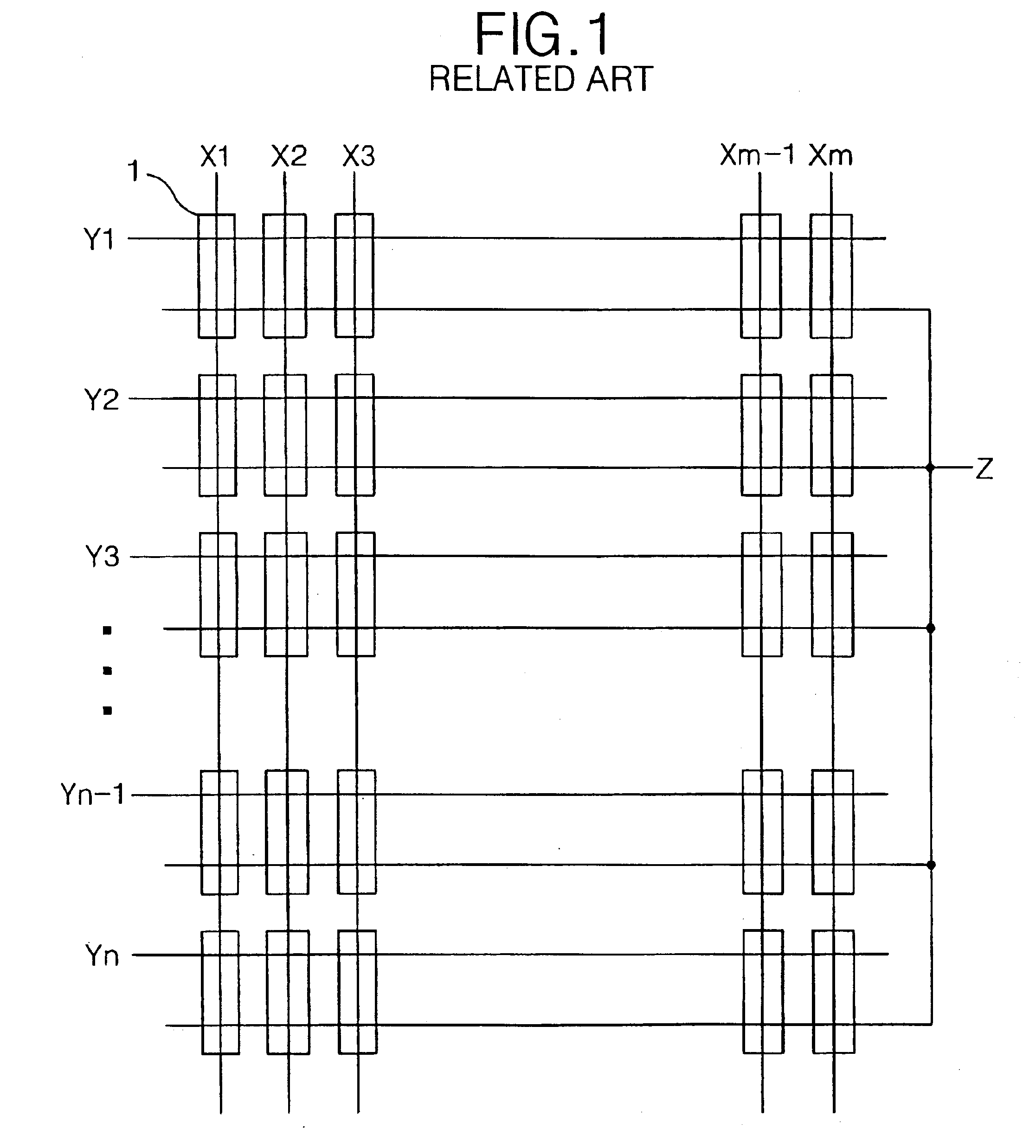
BACKGROUND OF THE INVENTION[0001]1. Field of the Invention[0002]This invention relates to a plasma display panel, and more particularly to an erasing method and apparatus that is capable of minimizing spurious wall charges left after an erasing discharge.[0003]2. Description of the Related Art[0004]Generally, a plasma display panel (PDP) excites and radiates a phosphorus material using an ultraviolet ray generated upon discharge of an inactive mixture gas such as He+Xe, Ne+Xe or He+Ne+Xe, to thereby display a picture. Such a PDP is easy to be made into a thin-film and large-dimension type. Moreover, the PDP provides a very improved picture quality owing to a recent technical development.[0005]Referring to FIG. 1, a discharge cell of a conventional three-electrode, AC surface-discharge PDP includes a scan electrode Y, a sustain electrode Z, and an address electrode X intersecting the scan electrode Y and the sustain electrode Z.[0006]Each intersection among the scan electrode Y, the ...

Claims


Application Information

Patent Timeline
IPC IPC(8): G09G3/28G09G3/288
CPCG09G3/2922G09G3/2927G09G2320/0238G09G2310/066
Inventor YUN, SANG JINKANG, SEONG HOCHUNG, MOON SHICKKOO, CHANG HWAN
Owner LG ELECTRONICS INC
Why Eureka
Try Eureka