Ribbon microphone
- Summary
- Abstract
- Description
- Claims
- Application Information
AI Technical Summary
Benefits of technology
Problems solved by technology
Method used
Image

Examples
Embodiment Construction
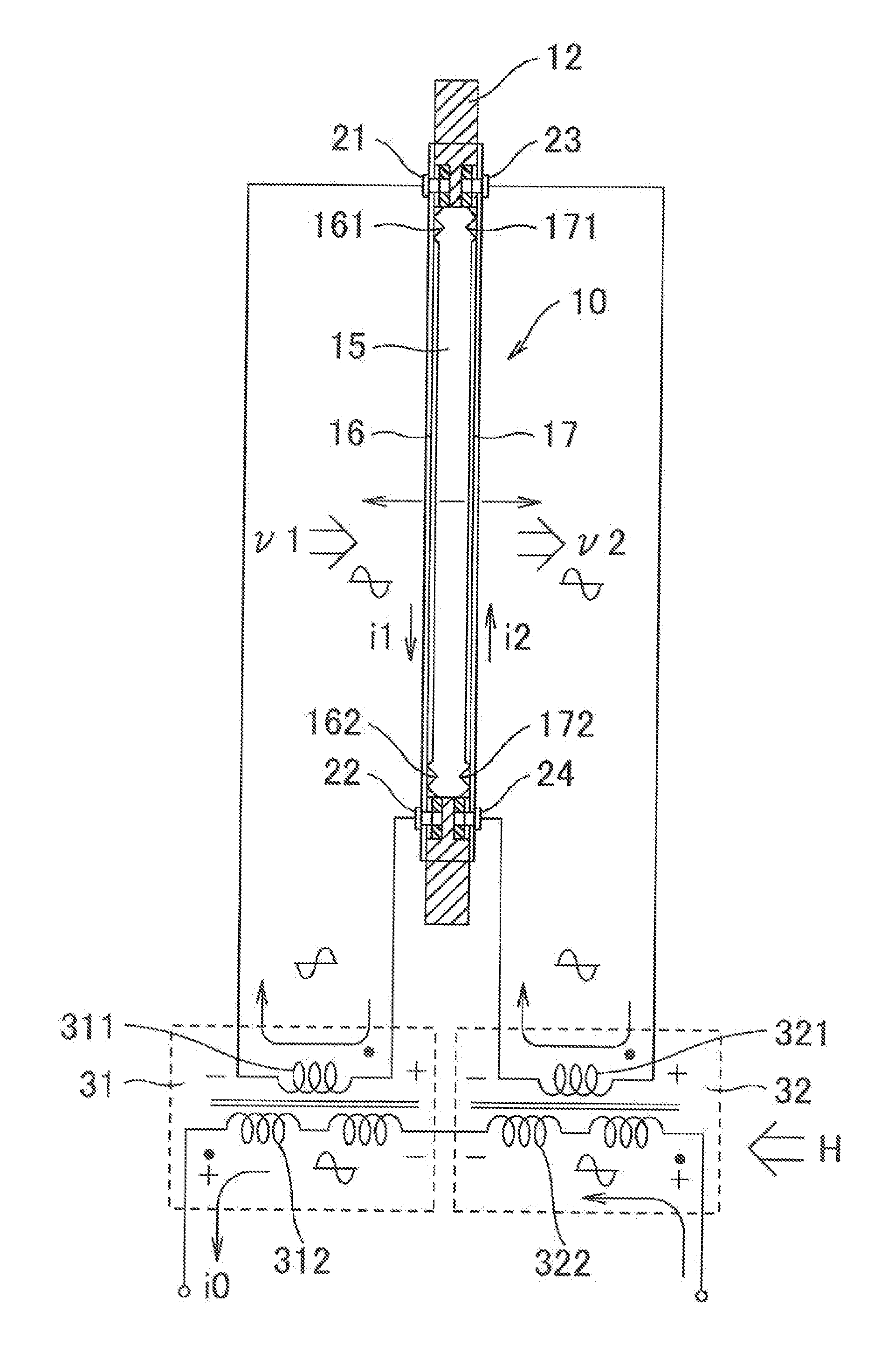
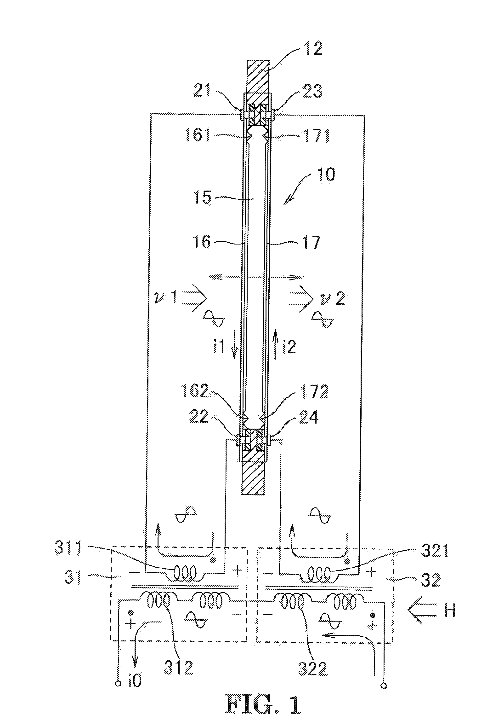
A ribbon microphone according to an embodiment of the present invention will be described below with reference to FIGS. 1 and 2. The ribbon microphone unit has the same physical configuration as that of the conventional example shown in FIG. 3, and the same components are denoted by the same reference numerals.
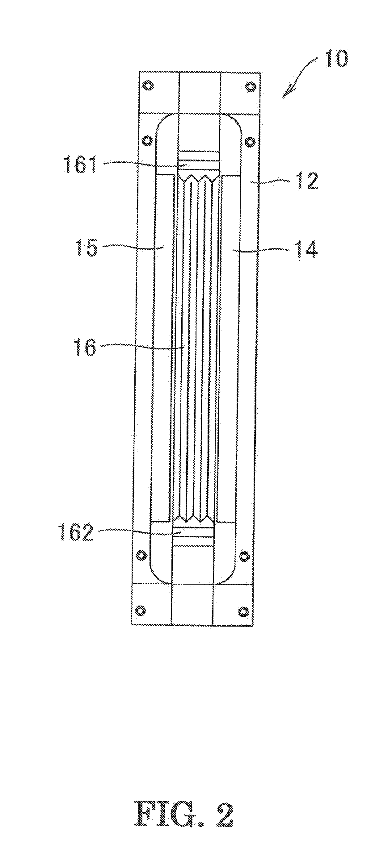
Referring to FIGS. 1 and 2, a ribbon microphone unit (hereinafter simply referred to as “unit”) 10 includes a yoke 12, two magnets 14 and 15, and two ribbons 16 and 17. The anteroposterior direction of the unit 10 corresponds to the lateral direction in FIG. 1. FIG. 2 shows the unit 10 as seen from the front. As shown in FIG. 2, the yoke 12 has a shape of a vertically long rectangular frame. The yoke 12 has rod-shaped magnets 14 and 15 that have a rectangular cross-section and are fixed to opposed left and right vertical inner walls, respectively, of the yoke 12 with a predetermined space therebetween in parallel with each other. These magnets 14 and 15 are magnetized in a dir...
PUM
 Abstract
Description
Claims
Application Information
 - R&D Engineer
- R&D Manager
- IP Professional
- Industry Leading Data Capabilities
- Powerful AI technology
- Patent DNA Extraction
Browse by: Latest US Patents, China's latest patents, Technical Efficacy Thesaurus, Application Domain, Technology Topic.
© 2024 PatSnap. All rights reserved.Legal|Privacy policy|Modern Slavery Act Transparency Statement|Sitemap