Transcranial electrostimulation apparatus and method

a transcranial electrostimulation and apparatus technology, applied in the field of transcranial electrostimulation apparatus and method, can solve the problems of electrostimulation devices even subjecting the wearer to pain, severe drawbacks in the comfort of wearers or patients, and burns the skin of wearers

Inactive Publication Date: 2005-06-07
NEXALIN TECH INC
View PDF32 Cites 15 Cited by
  • Summary
  • Abstract
  • Description
  • Claims
  • Application Information

AI Technical Summary

Benefits of technology

[0013]It is an object of this invention to provide an improved transcranial electrostimulation apparatus and method.
[0014]It is an additional object of this invention to provide an improved transcranial electrostimulation apparatus and method which does not employ direct current components.
[0015]It is another object of this invention to provide an improved transcranial electrostimulation apparatus and method employing only alternating current components.
[0016]It is a further object of this invention to provide an improved transcranial electrostimulation apparatus and method utilizing packets or groups of high frequency pulses which vary amplitude within each of the packets in a uniform manner and in which the p

Problems solved by technology

These original designs, although successfully employed for several different treatment modalities, had a severe drawback with regard to the comfort of the wearer or patient.
In some cases, these earlier cranial electrostimulation devices even subjected the wearer to pain.
It has been discovered that the reason for the discomfort of these earlier designs was a result of the use of direct current as part of the overall operation of the devices.
Without the presence of the pads (which were only required because of the presence of the DC current), such devices could either burn the skin of the wearer, or cause relatively intense pain before a usable level of the treatment modality o

Method used


Image

  • Transcranial electrostimulation apparatus and method
  • Transcranial electrostimulation apparatus and method
  • Transcranial electrostimulation apparatus and method

Examples


Embodiment Construction

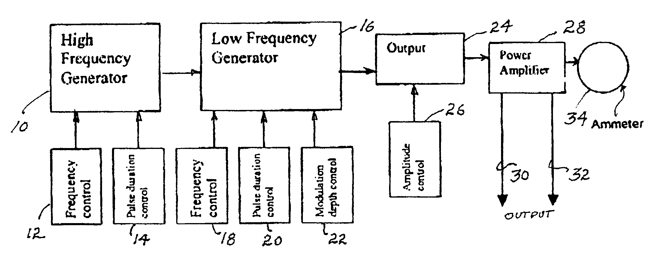
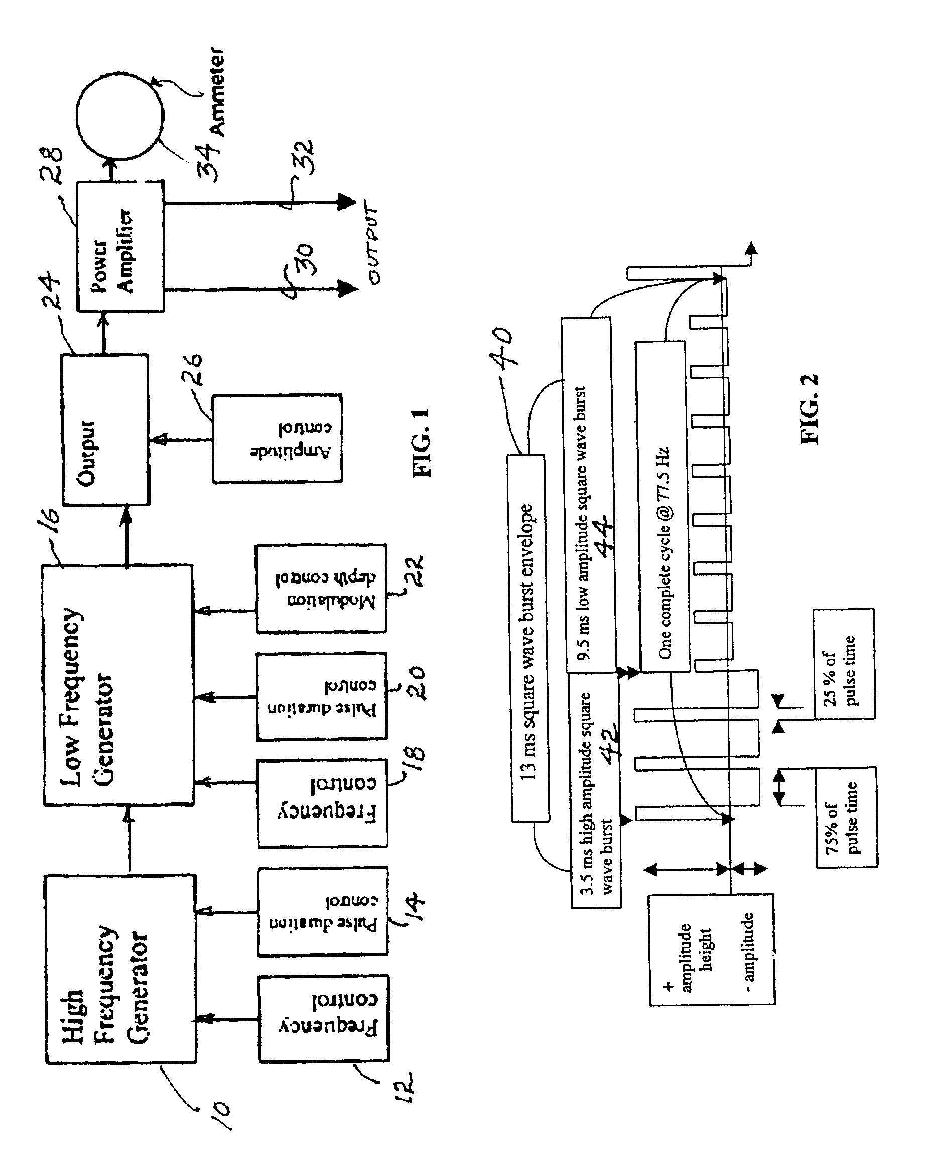
[0021]Reference now should be made to the drawings which illustrate a preferred embodiment of the invention and its operation. FIG. 1 is a diagrammatic representation of the salient operating features of circuitry implementations which produce a unique triple waveform asymmetry useful for various transcranial electrostimulation applications. The unique waveform which is described in detail in conjunction with FIG. 2 produces little to no discomfort to the user of the device.

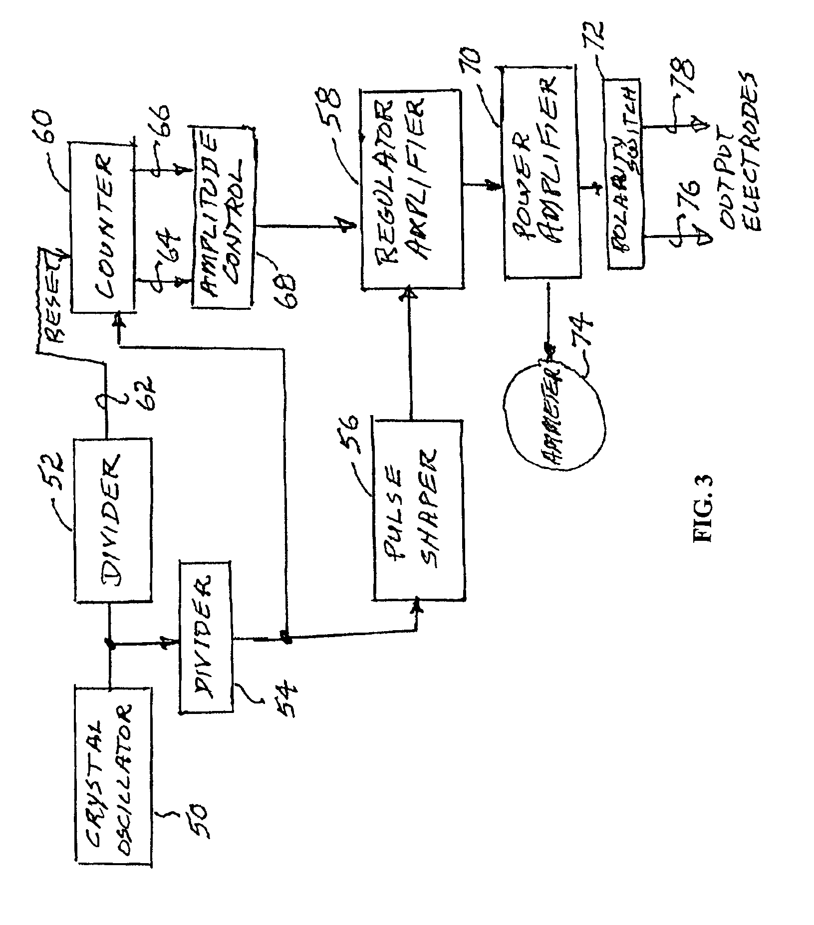
[0022]As illustrated in FIG. 1, the basic high frequency current signals are produced by a high frequency generator 10, which may employ a frequency control 12 and a pulse duration control 14 to establish the basic frequency and to provide the desired asymmetry between the positive and negative portions of each of the pulses produced by the generator 10. Typically, the generator 10 may include a crystal oscillator operating at 1,000 to 1,200 kHz, which then is divided down to the desired operating frequency of th...


PUM


Abstract

Transcranial electrostimulation apparatus and method includes a first generator of bipolar pulses of a first predetermined frequency. A source of modulating control signals, producing an output at a second frequency less than the first predetermined frequency, is used to cause the output pulses from the first generator of pulses to vary in amplitude in a predetermined asymmetrical pattern at the frequency of the modulating control signals, with the asymmetrical pattern of signals applied to output electrodes designed to be attached to the scalp of a patient.

Description

BACKGROUND[0001]Bio-electric stimulation apparatus has been developed for applying current pulses to a patient through electrodes located on opposite sides of the head of the patient. The current pulses at selected frequencies are applied to cause reaction with the central nervous system of the patient. Such devices, referred to as transcranial electrostimulation (TCES) or cranial electrostimulators (CES) have been used for a variety of non-invasive procedures, such as producing analgesic effects, reducing or controlling migraine headaches, and other applications of treatment and electro-anesthesia.[0002]Earliest prototypes of transcranial electrostimulation devices originated in Russia. These original designs, although successfully employed for several different treatment modalities, had a severe drawback with regard to the comfort of the wearer or patient. In some cases, these earlier cranial electrostimulation devices even subjected the wearer to pain. It has been discovered that...

Claims


Application Information

Patent Timeline
IPC IPC(8): A61N1/32A61N1/34
CPCA61N1/36021A61N1/32
Inventor KATSNELSON, YAKOV S.
Owner NEXALIN TECH INC
Why Eureka
Try Eureka