Systems and methods for flyback power converters with switching frequency and peak current adjustments based on changes in feedback signals

a technology of switching frequency and peak current, applied in the field of integrated circuits, can solve the problems that the power conversion system b>100/b> often cannot provide effective response to output loading change, and achieve the effects of increasing modulation frequency, increasing modulation frequency, and decreasing modulation frequency

Active Publication Date: 2013-02-07
ON BRIGHT ELECTRONICS SHANGHAI
View PDF6 Cites 108 Cited by
  • Summary
  • Abstract
  • Description
  • Claims
  • Application Information

AI Technical Summary

Benefits of technology

[0013]According to one embodiment, a system for regulating a power converter includes a first comparator, a pulse-width-modulation generator, a driver component, and a voltage-change-rate detection component. The first comparator is configured to receive a first input signal and a second input signal and generate a first comparison signal based on at least information associated with the first input signal and the second input signal, the first input signal being associated with at least a feedback signal related to an output current of the power converter. The pulse-width-modulation generator is configured to receive at least the first comparison signal and generate a modulation signal based on at least information associated with the first comparison signal, the modulation signal being associated with a modulation frequency. Moreover, the driver component is configured to receive the modulation signal and output a drive signal to a switch to adjust a primary current flowing through a primary winding of the power converter, the primary current being associated with a peak magnitude for each modulation period corresponding to the modulation frequency. Additionally, the voltage-change-rate detection component is configured to sample the feedback signal to generate a first sampled signal for a first modulation period and to sample the feedback signal to generate a second sampled signal for a second modulation period, the voltage-change-rate detection component being further configured to compare the first sampled signal and the second sampled signal in magnitude, the second modulation period being after the first modulation period. The system is further configured to determine whether the first sampled signal subtracted by the second sampled signal satisfies one or more first conditions. If the one or more first conditions are satisfied, the system is further configured to increase the modulation frequency and the peak magnitude related to the primary current.
[0014]According to another embodiment, a method for regulating a power converter includes receiving a first input signal and a second input signal, processing information associated with the first input signal and the second input signal, and generating a first comparison signal based on at least information associated with the first input signal and the second input signal, the first input signal being associated with at least a feedback signal related to an output current of the power converter. The method further includes receiving at least the first comparison signal, processing information associated with the first comparison signal, and generating a modulation signal based on at least information associated with the first comparison signal, the modulation signal being associated with a modulation frequency. In addition, the method includes receiving the modulation signal, processing information associated with the modulation signal, and outputting a drive signal to a switch to adjust a primary current flowing through a primary winding of the power converter, the primary current being associated with a peak magnitude for each modulation period corresponding to the modulation frequency. Moreover, the method includes sampling the feedback signal to generate a first sampled signal for a first modulation period, and sampling the feedback signal to generate a second sampled signal for a second modulation period, the second modulation period being after the first modulation period. Furthermore, the method includes determining whether the first sampled signal subtracted by the second sampled signal satisfies one or more first conditions, and if the one or more first conditions are satisfied, increasing the modulation frequency and the peak magnitude related to the primary current.
[0015]According to yet another embodiment, a system for regulating a power converter includes a first comparator, a pulse-width-modulation generator, a driver component, and a voltage-change-rate detection component. The first comparator is configured to receive a first input signal and a second input signal and generate a first comparison signal based on at least information associated with the first input signal and the second input signal, the first input signal being associated with at least a feedback signal related to an output current of the power converter. The pulse-width-modulation generator is configured to receive at least the first comparison signal and generate a modulation signal based on at least information associated with the first comparison signal, the modulation signal being associated with a modulation frequency. Moreover, the driver component is configured to receive the modulation signal and output a drive signal to a switch to adjust a primary current flowing through a primary winding of the power converter, the primary current being associated with a peak magnitude for each modulation period corresponding to the modulation frequency. In addition, the voltage-change-rate detection component is configured to sample the feedback signal to generate a first sampled signal for a first modulation period and to sample the feedback signal to generate a second sampled signal for a second modulation period, the voltage-change-rate detection component being further configured to compare the first sampled signal and the second sampled signal in magnitude, the second modulation period being after the first modulation period. The system is further configured to determine whether the first sampled signal subtracted by the second sampled signal is larger than a first threshold voltage, the first threshold voltage being larger than or equal to zero, and if the first sampled signal subtracted by the second sampled signal is determined to be larger than the first threshold voltage, increase the modulation frequency and the peak magnitude related to the primary current. Furthermore, the system is further configured to determine whether the second sampled signal subtracted by the first sampled signal is larger than a second threshold voltage, the second threshold voltage being larger than or equal to zero; and if the second sampled signal subtracted by the first sampled signal is determined to be larger than the second threshold voltage, decrease the modulation frequency and the peak magnitude related to the primary current.
[0016]According to yet another embodiment, a method for regulating a power converter includes receiving a first input signal and a second input signal, processing information associated with the first input signal and the second input signal, and generating a first comparison signal based on at least information associated with the first input signal and the second input signal, the first input signal being associated with at least a feedback signal related to an output current of the power converter. The method further includes receiving at least the first comparison signal, processing information associated with the first comparison signal, and generating a modulation signal based on at least information associated with the first comparison signal, the modulation signal being associated with a modulation frequency. In addition, the method includes receiving the modulation signal, processing information associated with the modulation signal, and outputting a drive signal to a switch to adjust a primary current flowing through a primary winding of the power converter, the primary current being associated with a peak magnitude for each modulation period corresponding to the modulation frequency. Moreover, the method includes sampling the feedback signal to generate a first sampled signal for a first modulation period, sampling the feedback signal to generate a second sampled signal for a second modulation period, the second modulation period being after the first modulation period. Furthermore, the method includes determining whether the first sampled signal subtracted by the second sampled signal is larger than a first threshold voltage, the first threshold voltage being larger than or equal to zero, and if the first sampled signal subtracted by the second sampled signal is determined to be larger than the first threshold voltage, increasing the modulation frequency and the peak magnitude related to the primary current. Additionally, the method includes determining whether the second sampled signal subtracted by the first sampled signal is larger than a second threshold voltage, the second threshold voltage being larger than or equal to zero, and if the second sampled signal subtracted by the first sampled signal is determined to be larger than the second threshold voltage, decreasing the modulation frequency and the peak magnitude related to the primary current.
[0017]Depending upon embodiment, one or more benefits may be achieved. These benefits and various additional objects, features and advantages of the present invention can be fully appreciated with reference to the detailed description and accompanying drawings that follow.

Problems solved by technology

But the power conversion system 100 often cannot provide effective response to output loading changes.

Method used


Image

  • Systems and methods for flyback power converters with switching frequency and peak current adjustments based on changes in feedback signals
  • Systems and methods for flyback power converters with switching frequency and peak current adjustments based on changes in feedback signals
  • Systems and methods for flyback power converters with switching frequency and peak current adjustments based on changes in feedback signals

Examples


Embodiment Construction

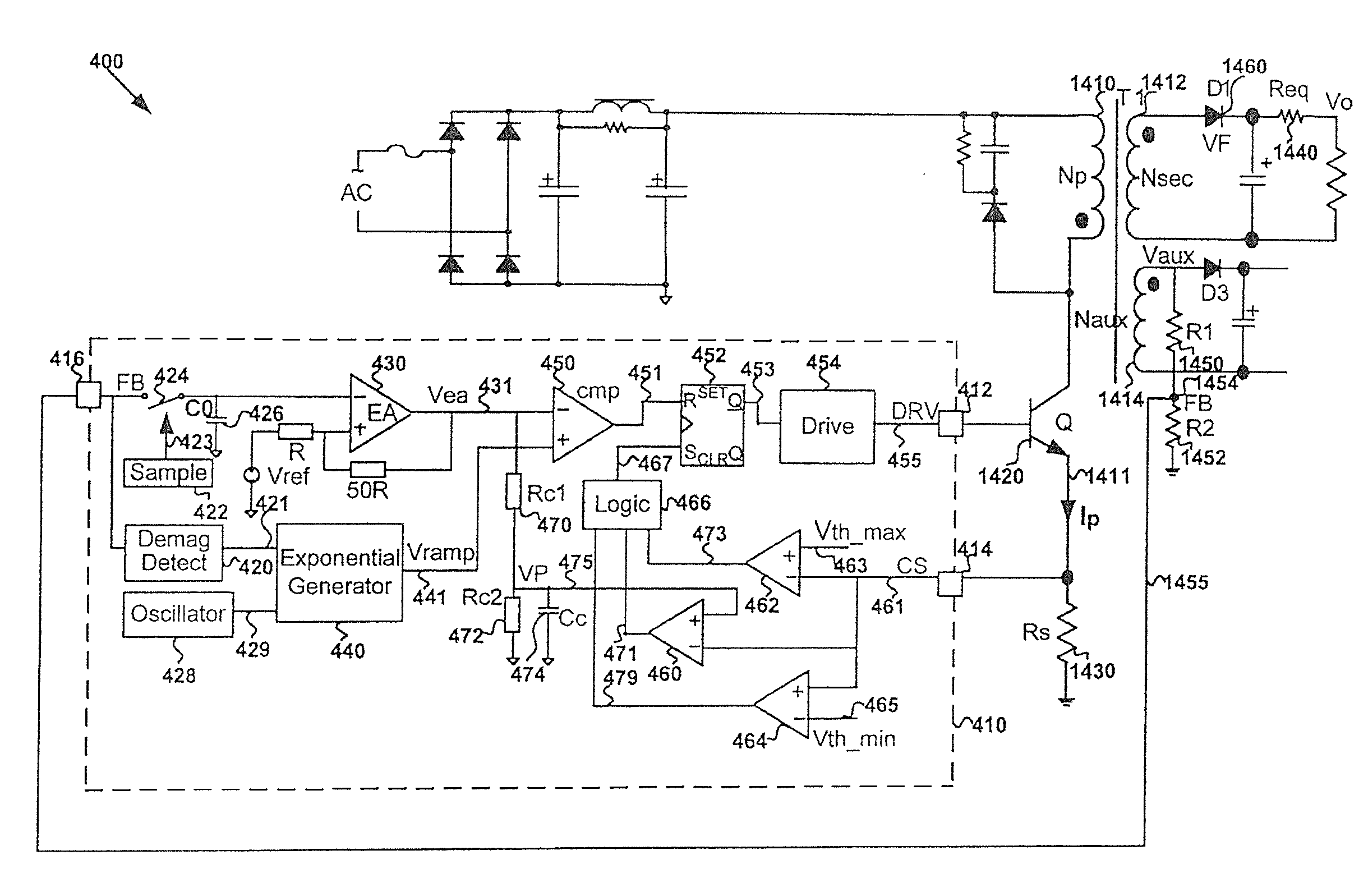
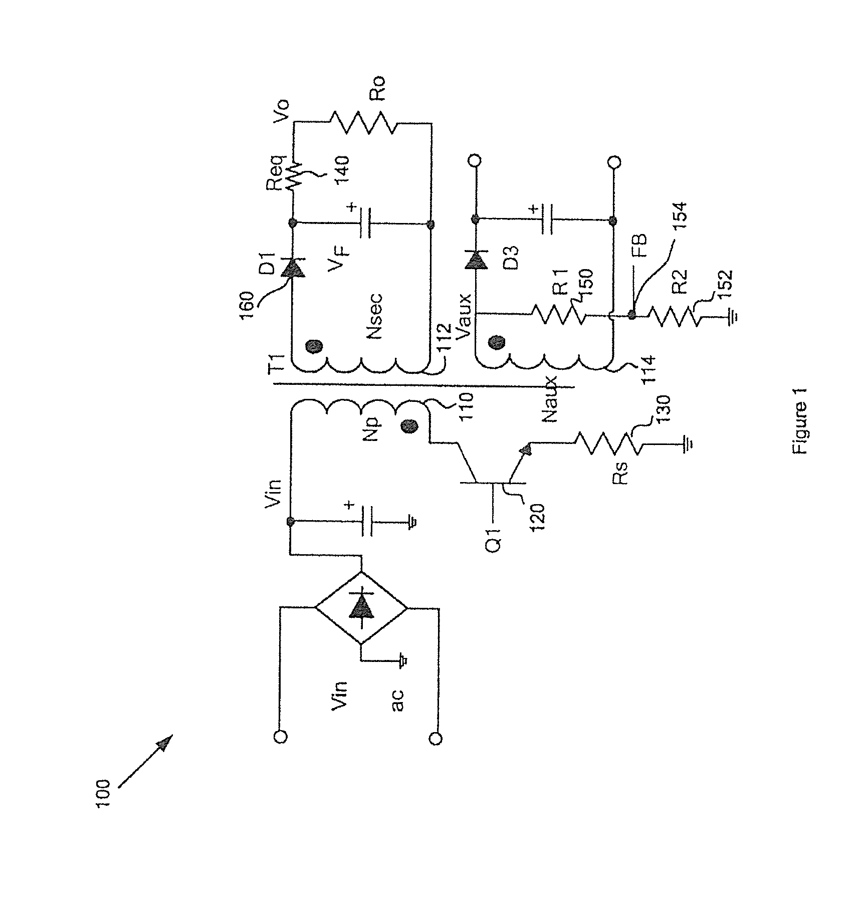
[0035]The present invention is directed to integrated circuits. More particularly, the invention provides switching frequency and peak current adjustments in response to loading changes. Merely by way of example, the invention has been applied to a flyback power converter. But it would be recognized that the invention has a much broader range of applicability.

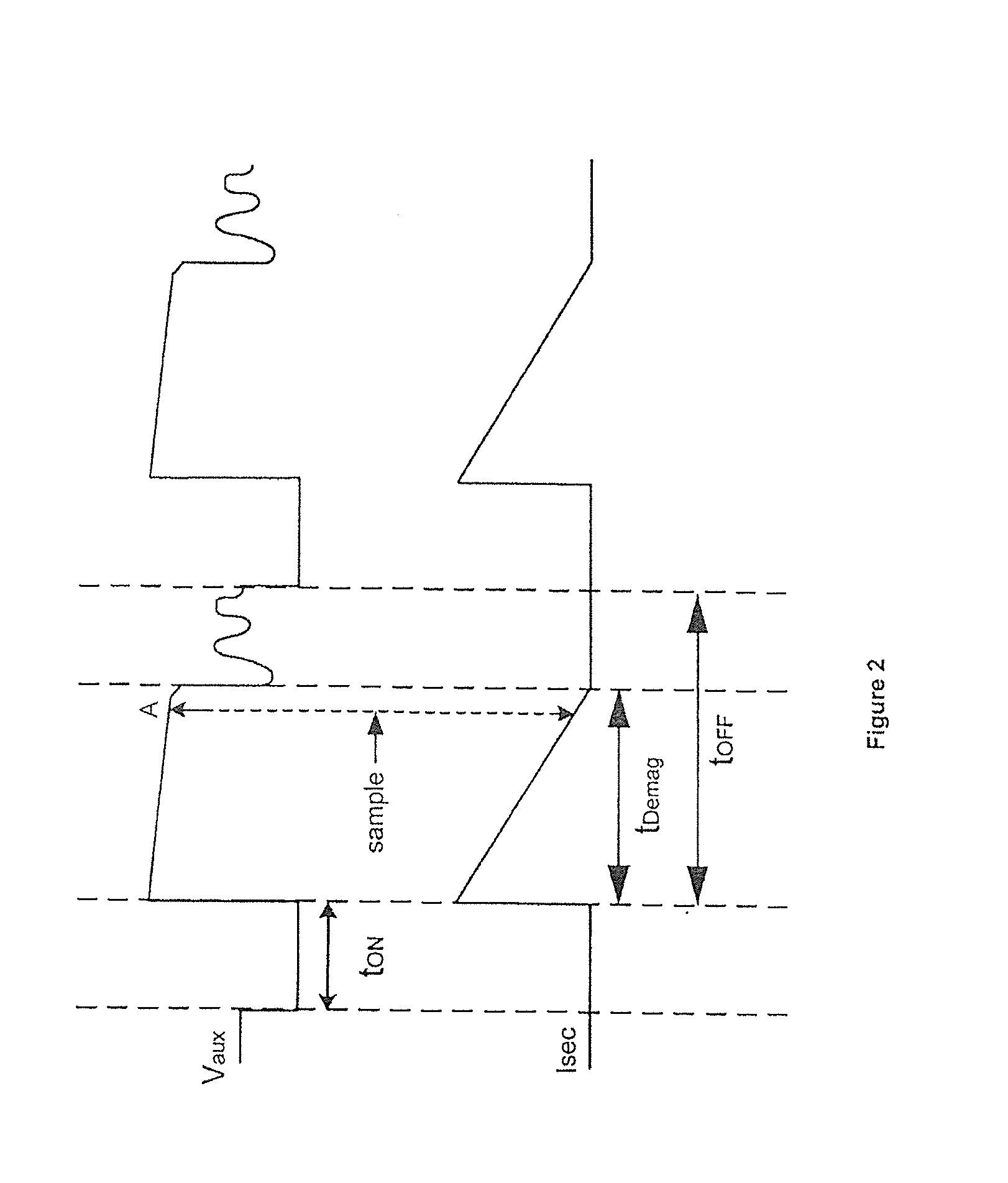
[0036]Referring to FIGS. 1 and 2, information about the output voltage of the power conversion system 100 often is sampled only once every switching period. The switching period is inversely proportional to the switching frequency, which usually is set low at no load or light load conditions to reduce power consumption. But the low switching frequency often leads to poor dynamic response for the power conversion system 100 if the load changes from no load or light load to full load. For example, if the switching frequency is several hundred Hz at no load or light load conditions, information about the output voltage of the powe...


PUM


Abstract

System and method for regulating a power converter. The system includes a first comparator configured to receive a first input signal and a second input signal and generate a first comparison signal based on at least information associated with the first input signal and the second input signal, a pulse-width-modulation generator configured to receive at least the first comparison signal and generate a modulation signal based on at least information associated with the first comparison signal, a driver component configured to receive the modulation signal and output a drive signal to a switch to adjust a primary current flowing through a primary winding of the power converter, and a voltage-change-rate detection component configured to sample the feedback signal to generate a first sampled signal for a first modulation period and to sample the feedback signal to generate a second sampled signal for a second modulation period.

Description

1. CROSS-REFERENCES TO RELATED APPLICATIONS[0001]This application claims priority to Chinese Patent Application No. 201110224933.5, filed Aug. 4, 2011, commonly assigned, incorporated by reference herein for all purposes.[0002]Additionally, this application is related to U.S. patent application Ser. Nos. 12 / 859,138 and 13 / 052,869, commonly assigned, incorporated by reference herein for all purposes.2. BACKGROUND OF THE INVENTION[0003]The present invention is directed to integrated circuits. More particularly, the invention provides switching frequency and peak current adjustments in response to loading changes. Merely by way of example, the invention has been applied to a flyback power converter. But it would be recognized that the invention has a much broader range of applicability.[0004]Generally, a conventional power conversion system often uses a transformer to isolate the input voltage on the primary side and the output voltage on the secondary side. To regulate the output volt...

Claims


Application Information

Patent Timeline
Patent Type & Authority Applications(United States)
IPC IPC(8): H02M3/335
CPCH02M3/33507Y02B70/16H02M2001/0032H02M1/0032Y02B70/10
Inventor LIN, YUANXIA, ZHENGLANZHANG, XIUHONGFANG, LIEYI
Owner ON BRIGHT ELECTRONICS SHANGHAI
Why Eureka
Try Eureka