Operating a vehicle control system

Inactive Publication Date: 2005-06-07
BWI +1
View PDF10 Cites 60 Cited by
  • Summary
  • Abstract
  • Description
  • Claims
  • Application Information

AI Technical Summary

Benefits of technology

[0006]A first aspect of the present invention provides a method of determining dynamic tire forces. A plurality of measured vehicle variables is determined. At least one suspension force is determined based on at least one of the determined measured vehicle variables. At least one tire vertical force is determined based on the at least one determined suspension force and at least one of the determined measured vehicle variables. At least one tire longitudinal force is determined based on at least one of the determined meas

Problems solved by technology

This strategy may have several shortcomings including the need for transmission of data from a rotating tire, a requirement of an excessive amount of data processing, and a lack of robustness due to a need for using tire stiffness characteristics in relating tire forces to measured deformation.
The tire stiffness characteristics may further be complicated by variations in pressure, rotation speed, and temperature.
The strategy disclosed by the '849 patent, however, is limited to a calculation of vertical tire forces and therefore does not provide

Method used


Image

  • Operating a vehicle control system
  • Operating a vehicle control system
  • Operating a vehicle control system

Examples


Embodiment Construction

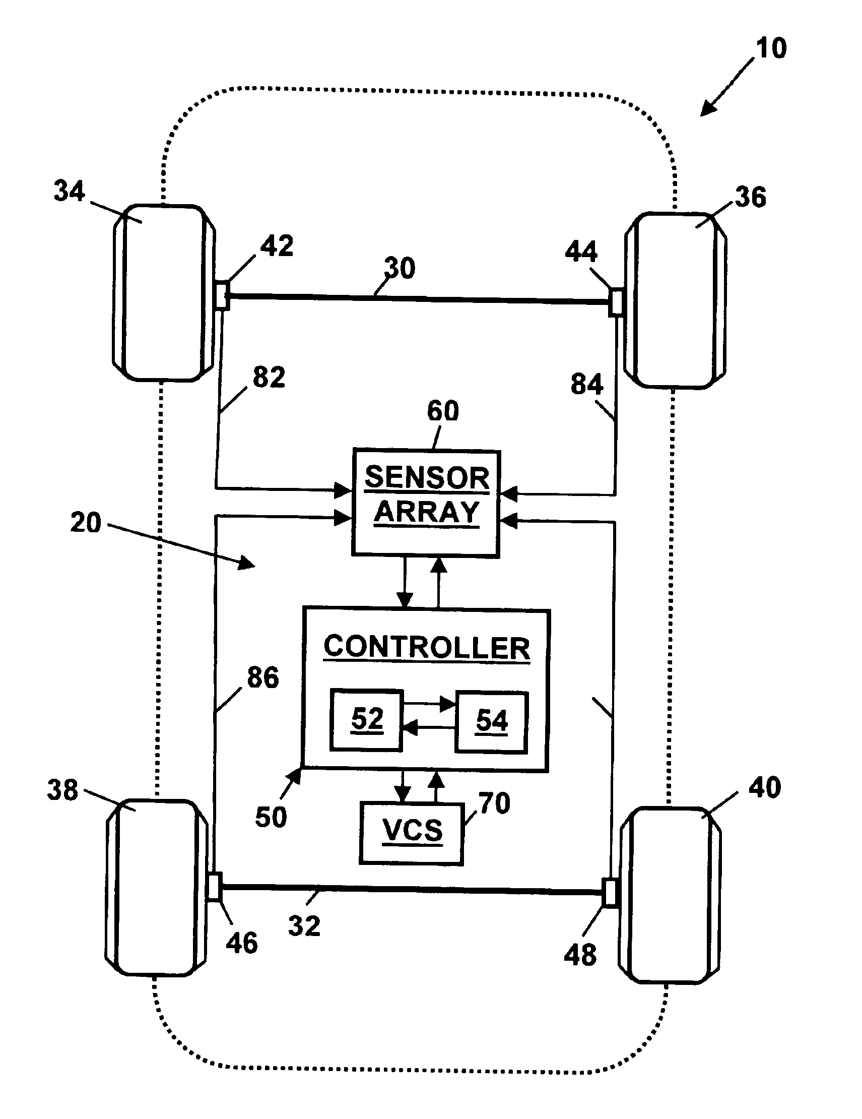
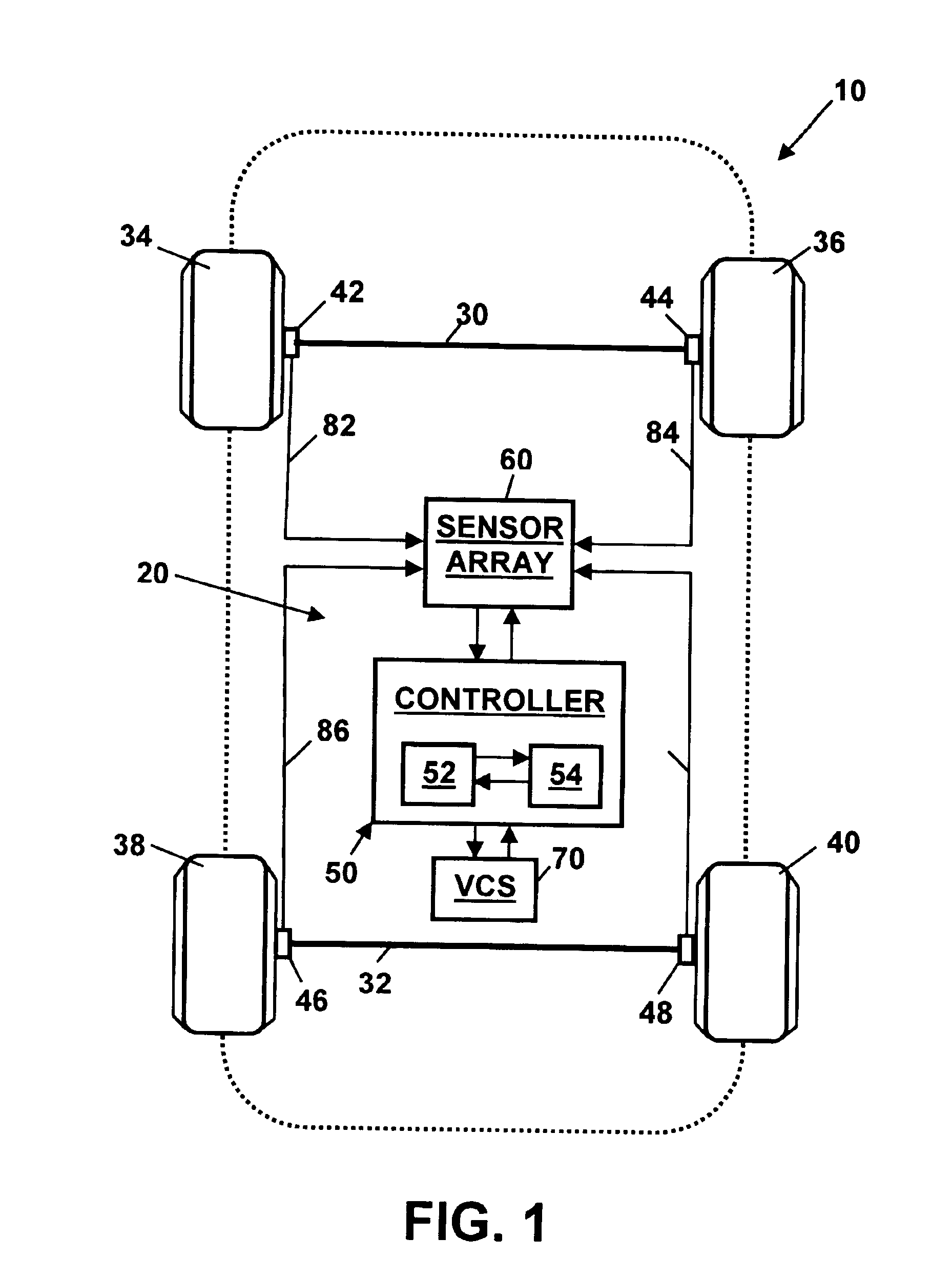
[0018]Referring to the drawings, wherein like reference numerals refer to like elements, FIG. 1 is a schematic view of a vehicle, shown generally by numeral 10, with a system 20 for determining dynamic tire forces in accordance with the present invention. Those skilled in the art will recognize that the vehicle 10 and system 20 may include a number of alternative designs and may be employed in a variety of applications. For example, as will be described below, the vehicle 10 may include various sensor “packages” as part of different system 20 embodiments.

[0019]In one embodiment, the vehicle 10 may include two axles 30, 32, each flanked by wheels 34, 36, 38, 40. Vehicle 10 may further include a controller 50 including a digital microprocessor 52 for executing an algorithm for determining dynamic tire forces in accordance with the present invention. Controller 50 may be programmed to process a plurality of input signals received from a sensor array 60 and a vehicle control system (VCS...


PUM


Abstract

The invention provides a method, a computer usable medium including a program, and a system for operating a vehicle control system. A plurality of measured vehicle variables is determined. At least one suspension force is determined based on at least one of the determined measured vehicle variables. At least one tire vertical force is determined based on the at least one determined suspension force and at least one of the determined measured vehicle variables. At least one tire longitudinal force is determined based on at least one of the determined measured vehicle variables. At least one axle lateral force is determined based on at least one of the determined measured vehicle variables. At least one tire lateral force is determined based on the at least one determined axle lateral force and the at least one determined tire vertical force. At least one control component of the vehicle control system is modulated based on the at least one determined tire vertical force, the at least one determined tire longitudinal force, and the at least one determined tire lateral force.

Description

TECHNICAL FIELD OF THE INVENTION[0001]The present invention relates generally to motor vehicles. More particularly, the invention relates to a strategy for operating a vehicle stability control system.BACKGROUND OF THE INVENTION[0002]The dynamics of ground vehicles are largely determined by forces between its tires and the road. Knowledge of these forces is beneficial for most active vehicle control systems. Several strategies have been developed for estimating tire forces in three axes (e.g., longitudinal, lateral, and vertical). For example, it has been reported that the measurement of deformation of a magnetized tire may be used to determine estimates of tire longitudinal and lateral forces. This strategy may have several shortcomings including the need for transmission of data from a rotating tire, a requirement of an excessive amount of data processing, and a lack of robustness due to a need for using tire stiffness characteristics in relating tire forces to measured deformatio...

Claims


Application Information

Patent Timeline
IPC IPC(8): G06G7/76G06G7/00B60T8/172
CPCB60T8/172B60T2240/06
Inventor HAC, ALEKSANDER B.
Owner BWI
Why Eureka
Try Eureka