Method and system for allocating protection path resources

a protection path and resource allocation technology, applied in the field of communication networks, can solve problems such as reducing the available bandwidth of working paths

Active Publication Date: 2005-06-07
CIENA
View PDF10 Cites 67 Cited by
  • Summary
  • Abstract
  • Description
  • Claims
  • Application Information

AI Technical Summary

Benefits of technology

[0007]An embodiment of the invention is a method of allocating protection path resources including defining a working path and obtaining a link vector for each of a plurality of protection paths. The link vector includes a plurality of link vector elements. A proposed link vector is determined for each of the protection paths. The proposed link vector includes a plurality of proposed link vector elements and is indicative of allocating a respective protection path to the working path. A m

Problems solved by technology

Whenever protection path bandwidth is increased, t

Method used


Image

  • Method and system for allocating protection path resources
  • Method and system for allocating protection path resources
  • Method and system for allocating protection path resources

Examples


Embodiment Construction

[0015]The following detailed description of the invention refers to the accompanying drawings. The same reference numbers in different drawings identify the same or similar elements. Also, the following detailed description does not limit the invention. Instead, the scope of the invention is defined by the appended claims and equivalents thereof.

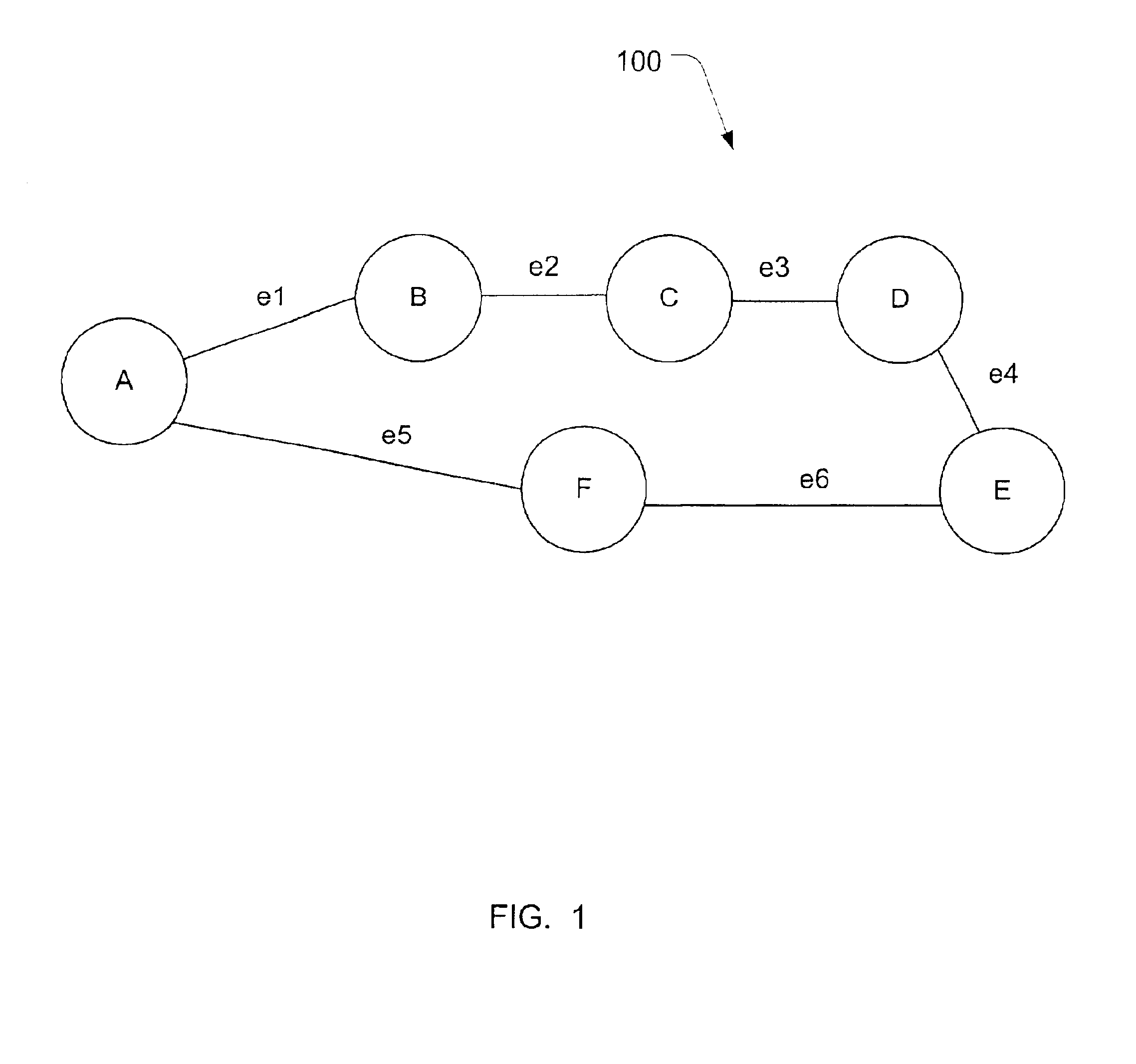
[0016]FIG. 1 is a block diagram of a portion of an exemplary network 100. FIG. 1 depicts an exemplary arrangement and is presented to facilitate description of the invention. Network 100 includes a plurality of communicating network elements labeled A-F. Network 100 may be any type of communications network (e.g., an optical network) using a variety of communications formats such as MPLS, ATM, frame relay, etc. The network elements A-F may be any type of known network devices such as routers, switches, transceivers, repeaters, add-drop multiplexers, etc.

[0017]Network elements A-F are connected by a plurality of links referenced as e1-e6. Lin...


PUM


Abstract

An embodiment of the invention is a method of allocating protection path resources including defining a working path and obtaining a link vector for each of a plurality of protection paths. The link vector includes a plurality of link vector elements. A proposed link vector is determined for each of the protection paths. The proposed link vector includes a plurality of proposed link vector elements and is indicative of allocating a respective protection path to the working path. A maximum link vector element is determined and a maximum proposed link vector element is determined. A link cost is determined based on a difference between the maximum proposed link vector element and the maximum link vector element. A path cost is determined for at least two protection paths based on a sum of link costs associated with a respective protection path. One of the at least two protection paths having the minimum path cost is selected to provide protection for the working path.

Description

CROSS REFERENCE TO RELATED APPLICATIONS[0001]This application claims the benefit of U.S. Provisional patent application, Protection Path Sharing Schemed, Ser. No. 60 / 303,495, filed Jul. 6, 2001, the entire contents of which are incorporated herein by reference.BACKGROUND OF THE INVENTION[0002]1. Field of Invention[0003]The invention relates generally to communications networks and in particular to a method and system for allocating protection path resources in a communications network.[0004]2. Description of Related Art[0005]In existing communications networks, protection paths are provided for one or more working paths in the event the working path fails. A variety of protection topologies exist and include assigning a single protection path for each working path (referred to as 1:1) or multiple working paths sharing a protection path (referred to as 1:N). Protection topologies also vary depending on the network topology and may be implemented in linear, ring or mesh configurations...

Claims


Application Information

Patent Timeline
IPC IPC(8): G01R31/08G06F15/16G06F15/173H04J3/14H04L1/00H04J1/16H04J1/00H04L12/26H04L12/24H04L12/28H04LH04L12/56
CPCH04L45/00H04L45/30H04L45/22
Inventor SINHA, RAKESH KUMAR
Owner CIENA
Why Eureka
Try Eureka