Visual indicator for an aerosol medication delivery apparatus and system

a technology of aerosol medication and visual indicator, which is applied in the direction of medical devices, inhalators, other medical devices, etc., can solve the problems of affecting the viewing experience, difficult to do, and lack of visual indication to alert the caregiver

Inactive Publication Date: 2005-06-14
TRUDELL MEDICAL INT INC
View PDF58 Cites 60 Cited by
  • Summary
  • Abstract
  • Description
  • Claims
  • Application Information

AI Technical Summary

Benefits of technology

[0012]One aspect of the present invention regards a delivery system that includes a chamber that contains a substance in an interior volume of space formed within said chamber and an opening that receives the substance located in said volume of space and introduces the substance to a downstream path upon which the substance primarily flows along. An interface that receives the substance from the opening, the interface has a viewing port that prevents substantially non-ambient atmosphere gases and substances from escaping therefrom and that allows visualization of an internal portion of the interface. A flow indicator is positioned within the interface so as to be viewed via the viewing port and is positioned so as to not substantially interfere with a flow of the substance along the path.

Problems solved by technology

One problem that currently exists with many aerosol delivery systems is that there is a lack of a visual indication to alert a caregiver when a patient is inhaling.
This is difficult to do in the case of low tidal volumes when the valve will only move a minor amount.
If the chamber has an accumulation of drug deposited on the walls then this further impedes the viewing.
At lower tidal volumes the petals will lift a small amount, but this can be difficult to see since there are numerous supporting ribs directly in the line of sight.
Another problem that occasionally occurs, when the interface includes a mask, is a poor seal between the patient's face and the mask.
Such a poor seal may adversely affect the delivery of aerosolized medication to the patient.

Method used


Image

  • Visual indicator for an aerosol medication delivery apparatus and system
  • Visual indicator for an aerosol medication delivery apparatus and system
  • Visual indicator for an aerosol medication delivery apparatus and system

Examples


Embodiment Construction

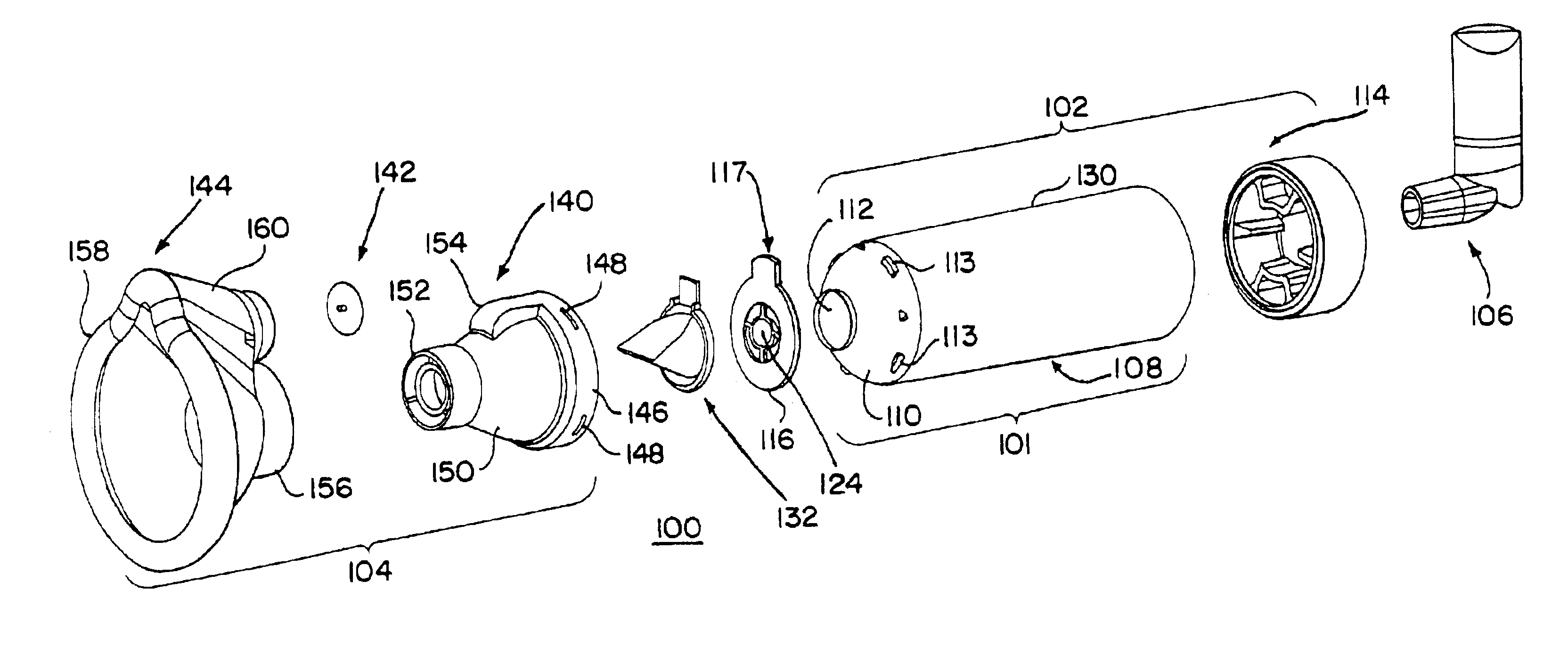
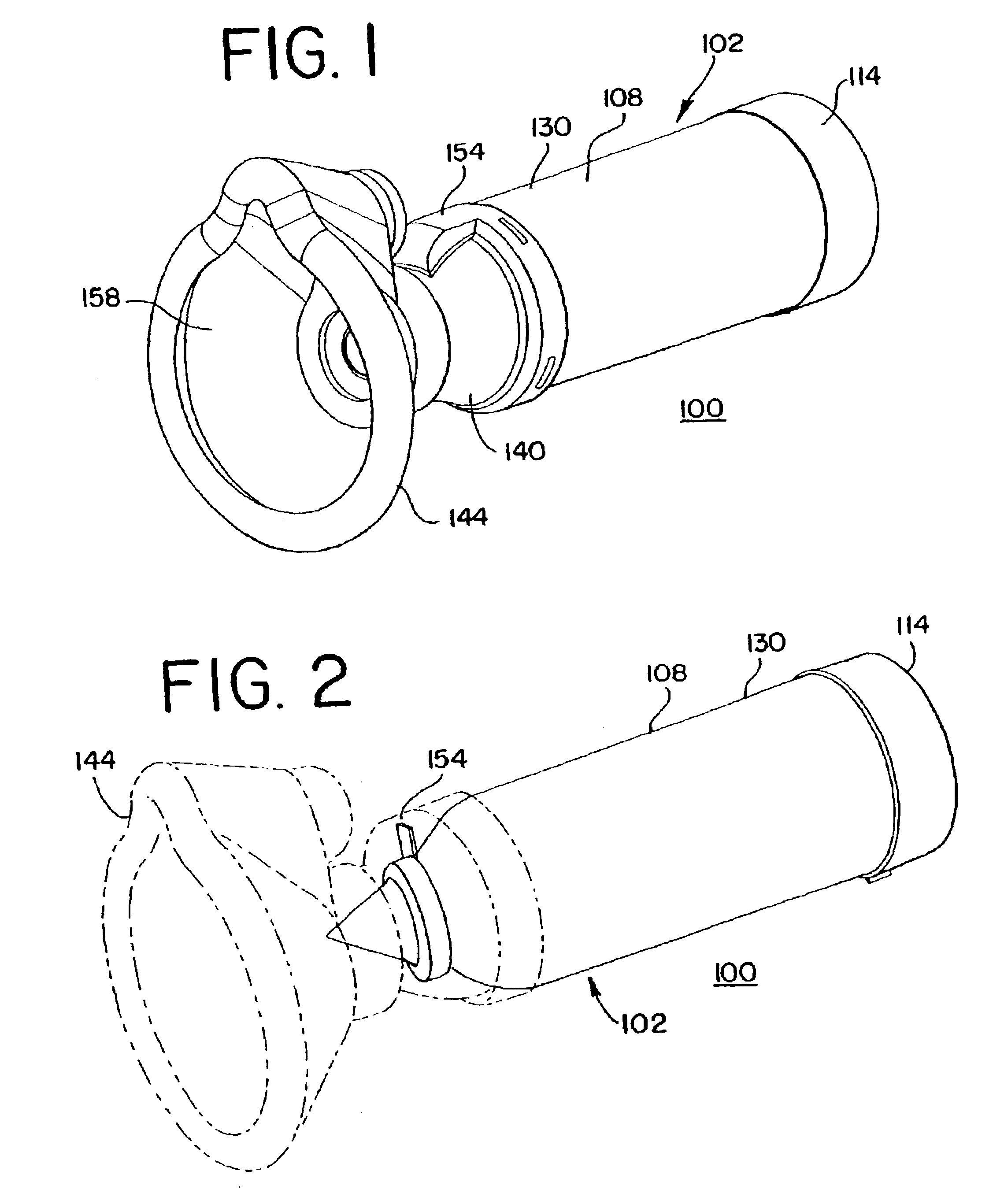
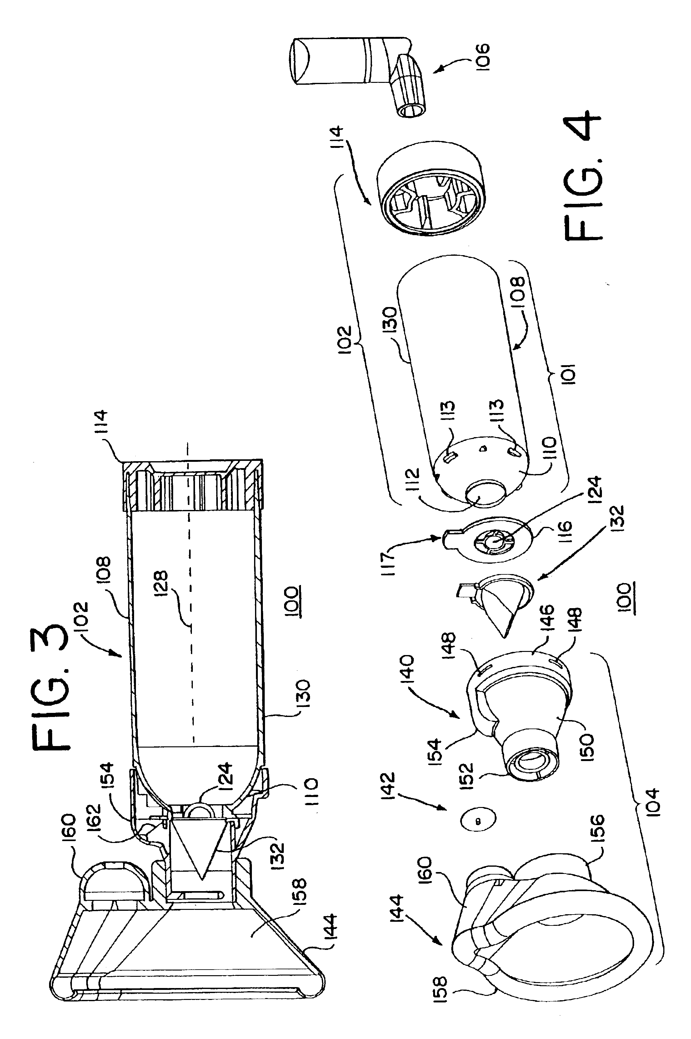
[0062]FIGS. 1-11, 16-21 and 25-29 show an embodiment of an aerosol delivery system 100. The system 100 includes a holding chamber or conduit 102, an interface 104, a retaining disc 116, an inhalation valve 132 and a source of a substance, such as a pMDI canister 106, attached to the rear end of the holding chamber 102.

[0063]As shown in FIGS. 1≧4 and 27-34, the holding chamber 102 includes a chamber housing 108 that has a generally cylindrical cross-sectional shape that defines an interior volume of space for receipt therein of aerosolized medication from the pMDI 106. A front end of the chamber housing 108 includes a dome-shaped head piece 110 that includes a central circular opening 112 that is in fluid communication with the interior volume of space of the chamber housing 108. The opening 112 defines the periphery of a flow path as it exits the opening. The head piece 110 further includes a plurality of engagement tabs 113, whose function will be described below. A rear end of the...


PUM

PropertyMeasurementUnit
outer radiusaaaaaaaaaa
arcuate lengthaaaaaaaaaa

Abstract

A flow indicating system that includes a conduit that contains a substance, wherein the conduit defines a path along which the substance primarily flows and a viewing port attached to the conduit and the viewing port prevents substantially non-ambient atmosphere gases and substances from escaping therefrom and allows visualization of an internal space defined by the viewing port. A flow indicator that is positioned within the conduit so as to be viewed via the viewing port and is positioned so as to not to substantially interfere with a flow of the substance along the path.

Description

[0001]This application claims the benefit of U.S. Provisional Patent Application 60 / 382,227, filed May 21, 2002, the entire disclosure of which is hereby incorporated herein by reference.BACKGROUND OF THE INVENTION[0002]1. Field of the Invention[0003]The present invention relates to a visual indicator for an aerosol medication delivery apparatus and system used for administering a dosage of a substance in aerosol form to a patient.[0004]2. Discussion of Related Art[0005]The use of an aerosol medication delivery apparatus and system to administer medication in aerosol form to a patient's lungs by inhalation (hereinafter “aerosol delivery system(s)”) is well known in the art. As used herein: the term “substance” includes, but is not limited to, any substance that has a therapeutic benefit, including, without limitation, any medication; the term “patient” includes humans and animals; and the term “aerosol delivery system(s)” includes pressurized metered-dose inhalers (pMDIs), pMDI add-...

Claims


Application Information

Patent Timeline
Patent Type & Authority Patents(United States)
IPC IPC(8): A61M16/20A61M16/06A61M15/00
CPCA61M16/06A61M16/208A61M16/14A61M15/0016A61M15/0018A61M15/009A61M15/0086A61M2205/583Y10T29/49826A61M16/0616A61M2207/00
Inventor BRUCE, SARAHSCHMIDT, JAMES N.
Owner TRUDELL MEDICAL INT INC
Why Eureka
Try Eureka