LED lighting fixture

a technology of led lighting fixtures and led light, which is applied in the direction of lighting support devices, special-purpose vessels, instruments, etc., can solve the problems of increasing the diameter of the lens, affecting the cost of the lens,

Inactive Publication Date: 2005-06-14
ZENI LITE BUOY
View PDF9 Cites 67 Cited by
  • Summary
  • Abstract
  • Description
  • Claims
  • Application Information

AI Technical Summary

Benefits of technology

[0009]The object of the present invention is to provide an LED lighting fixture that makes the horizontal light distribution nearly concentric using as few LEDs as possible, thereby realizing uniform and horizontal light distribution.
[0010]Another object of the present invention is to provide an LED lighting fixture in which the size and weight of the lighting fixture is as small as possible by minimizing the number of LEDs required.
[0013]The present invention solves this problem by employing newly developed LEDs with an extremely wide horizontal divergence angle so that it is possible to make a lighting fixture for navigational aid without using a lens or lenses.
[0015]By way the arrangement of the LEDs and lens as described above, it is possible to make the horizontal light distribution of the LEDs nearly concentric and uniform while using a small number of LEDs.

Problems solved by technology

However, using a lens or lenses is itself a cost factor.
Firstly, a process is required to make a lens or lenses.
Secondly, because LEDs need to be arranged at the focal point of the lens, increasing the number of LEDs per tier necessitates that the diameter of the lens be increased.

Method used


Image

  • LED lighting fixture
  • LED lighting fixture
  • LED lighting fixture

Examples


Embodiment Construction

[0024]The principle of the present invention will be explained first with reference to FIGS. 4(a) through 4(c).

[0025]FIG. 4(a) shows the light distribution characteristics of conventional LEDs having a divergence angle of 30° in both the horizontal and perpendicular directions. FIG. 4(b) shows light distribution characteristics of elliptically light distributing LEDs having a horizontal divergence angle of 70° and a perpendicular divergence angle of 30°, so that the LEDs are arranged so that the wider divergence angle of each LED is horizontally oriented. Comparing these two, it can be recognized that the radiation range is larger in the case of FIG. 4(b) than in the case of FIG. 4(a) even though the same number (six) of LEDs are used.

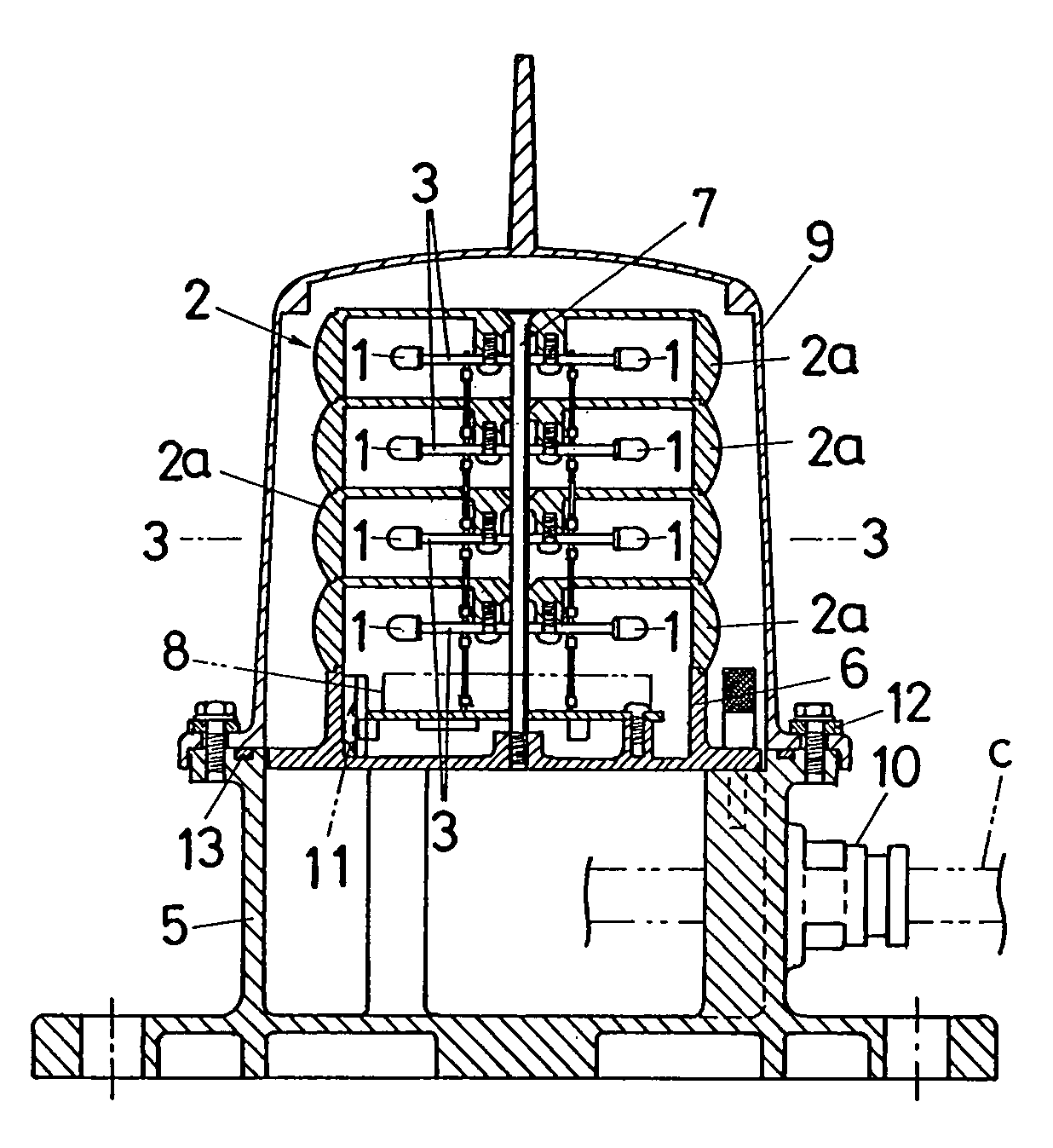
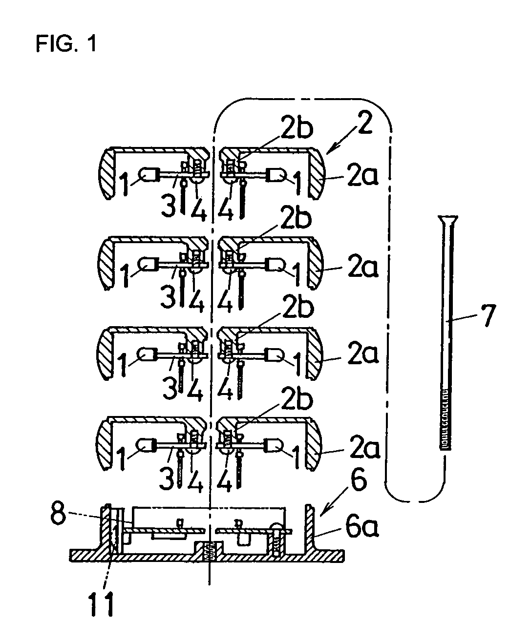
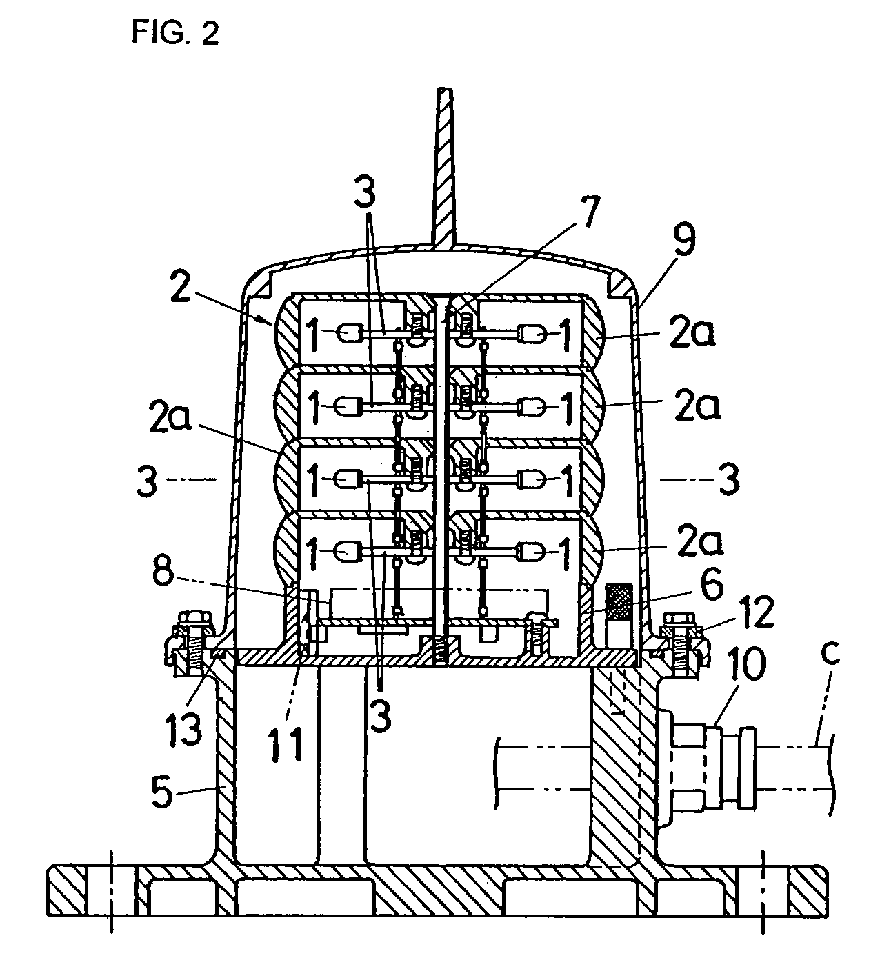
[0026]When several LEDs are arranged radially around a horizontal circumference or arranged circularly on a horizontal plane, and a lens 2 converging the light from the LEDs in the horizontal circumferential direction is provided around the LEDs, a hig...


PUM


Abstract

In the centers of each of unit-type lenses that constitute a lens, a plurality of elliptically light distributing LEDs being arranged circularly in a horizontal direction in such a way that a wider divergence angle of each LED is set to be oriented horizontally. The unit-type lenses are stacked and fastened by a screw that runs through the bosses of the unit-type lenses.

Description

BACKGROUND OF THE INVENTION[0001]1. Field of the Invention[0002]The present invention relates to a lighting fixture used as a navigational aid, using light-emitting diodes (LEDs) having different divergence angles in the horizontal and perpendicular directions, i.e., a so-called elliptic light distribution, as the light source.[0003]2. Prior Art[0004]LEDs are widely used as light sources in navigational aids on account of their low power consumption and low failure rate.[0005]Because the light-emitting energy of a single LED is small, a tubular lens is typically used to surround several LEDs in order to concentrate their light by convergence, thereby increasing their effective illumination. However, if LEDs with a high convergence rate are arranged in a large array, their light is not distributed uniformly in the horizontal circumferential direction, which is how the light should ideally be distributed. Therefore, in order to distribute the light horizontally and uniformly, LEDs wit...

Claims


Application Information

Patent Timeline
Patent Type & Authority Patents(United States)
IPC IPC(8): F21V5/04F21V5/00F21S8/00F21V19/00B63B22/16F21S2/00F21V14/00F21V15/01F21Y101/02G02B3/08H01L33/58
CPCF21V5/046F21V19/0055F21Y2111/008F21Y2101/02Y10S362/80F21W2111/00F21Y2107/60F21Y2115/10
Inventor TAKEYASU, MITSURUARIMURA, TADAHIROTABATA, YOSHIHISAKAIBARA, DAISUKE
Owner ZENI LITE BUOY
Why Eureka
Try Eureka