Eureka AIR delivers breakthrough ideas for toughest innovation challenges, trusted by R&D personnel around the world.

Device and method for irradiation

Inactive Publication Date: 2005-06-14
FOSS ANALYTICAL AB (SE)
View PDF12 Cites 0 Cited by
  • Summary
  • Abstract
  • Description
  • Claims
  • Application Information

AI Technical Summary

Benefits of technology

[0009]It is an object of the invention to solve the problems with sample irradiation described above. It is a further object of the invention to provide an easy way of irradiating moving particle samples.

Problems solved by technology

This makes movement of the sensor according to the second alternative complicated and undesirable.
If several objects are measured in one recording according to the third alternative, it is often difficult to record variations among the objects.
Further, certain set-ups for the irradiation are impossible to achieve for this alternative.
It is desired that a fixed light source be arranged at the measurement position, but for some irradiation arrangements this could be difficult to achieve.
These radiation sources could have varying characteristics, which will affect the measurements and deteriorate the reliability of the measurements.
Further, power supply has to be provided to a moving radiation source, which makes the arrangement complicated.

Method used


Image

  • Device and method for irradiation
  • Device and method for irradiation
  • Device and method for irradiation

Examples


Embodiment Construction

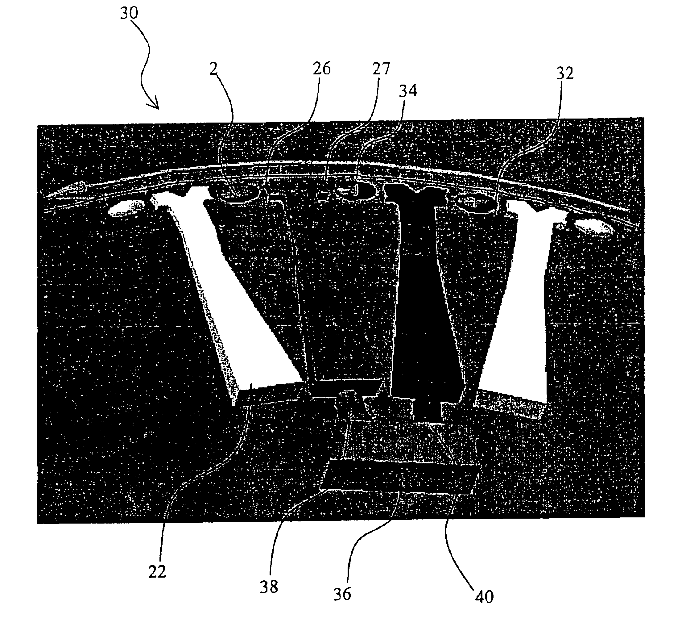
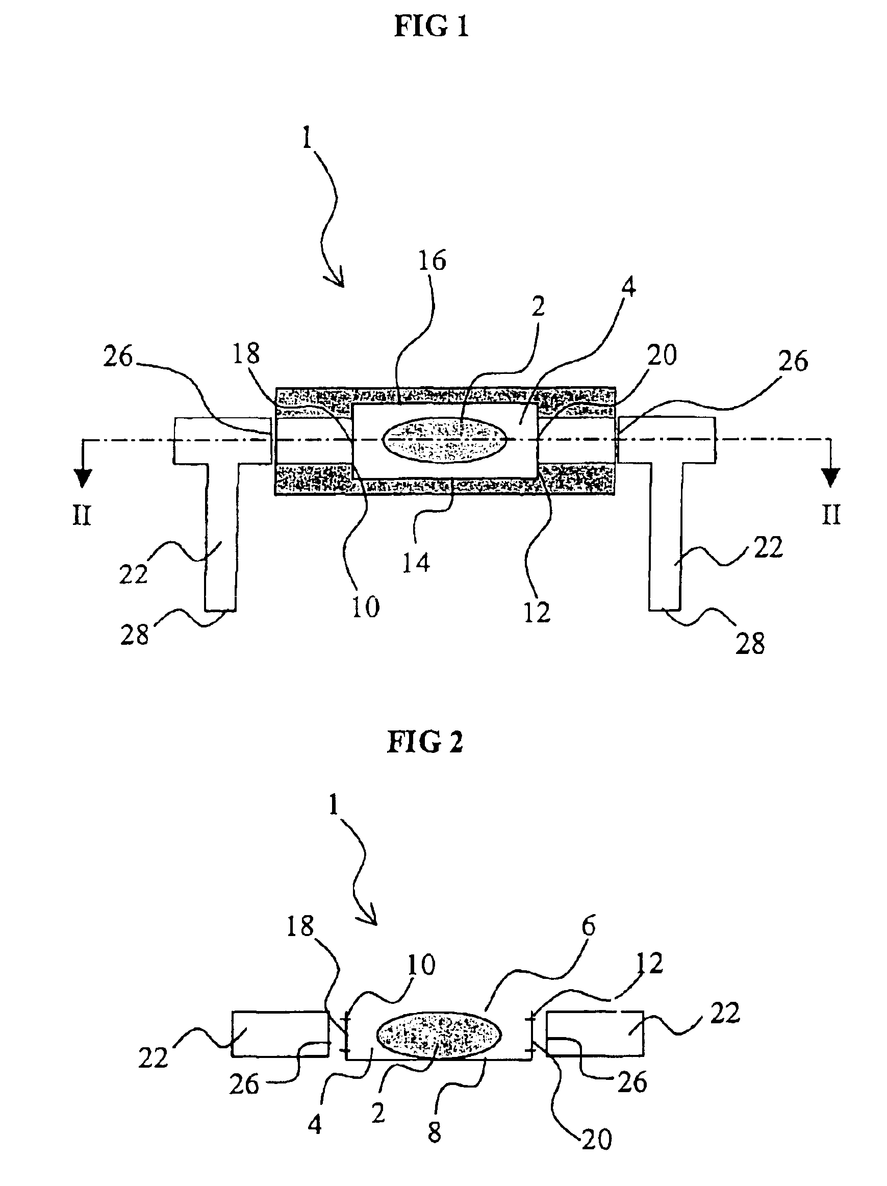
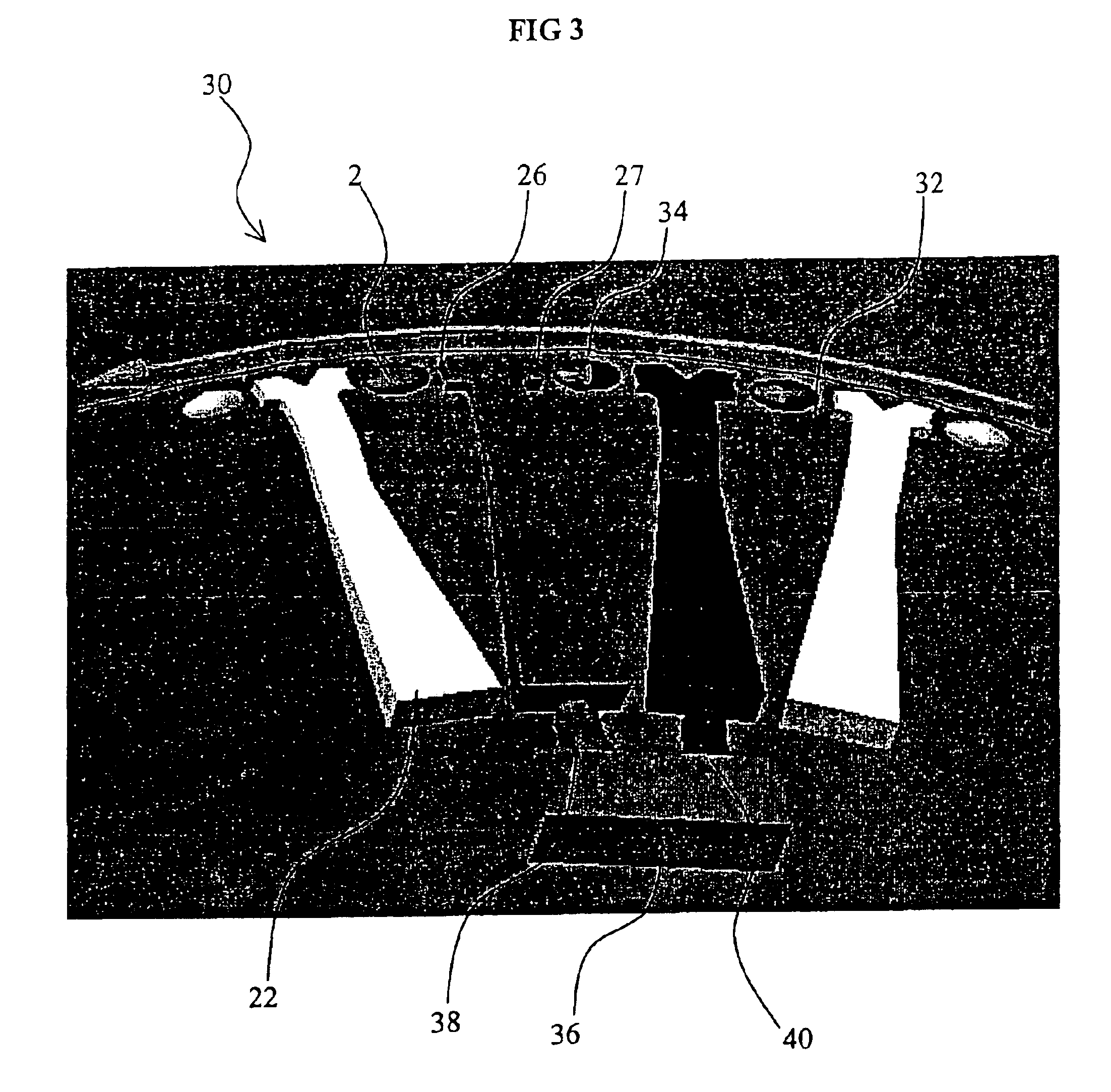
[0029]In FIGS. 1 and 2 a sample holder 1 for transporting a particle sample 2 is shown. The particle sample 2 comprises one kernel of an agricultural product that is to be analyzed. The sample holder 1 forms a cavity 4, into which a particle sample 2 falls. The cavity 4 is essentially formed like a particle for controlling the orientation of the particle. Thus, a particle that falls into the cavity 4 of the sample holder 1 is oriented in a specified way. This could be used in the analysis of the particle for easily obtaining information about the quality of the particle.

[0030]The cavity 4 of the sample holder 1 has an upper opening 6 through which the particles can fall into the cavity 4. The cavity 4 further has a bottom 8 for carrying the particle sample 2 and side walls 10, 12, 14, 16 restricting the movements and the orientation of the sample 2 in the cavity 4. In order to control the orientation of an elongate particle, the cavity 4 has two short side walls 10, 12 and two long ...


PUM


Abstract

A device for irradiation of small particles, such as grains from cereals and like crops, for analysis of the quality of the particles, comprises a sample-feeding carrier (30), which has sample holders and is adapted to take up particle samples (2), which each comprise at least one particle, in the sample holders and transport the particle samples (2) to a place for irradiation (34). The device further comprises a radiating device (36) emitting electromagnetic radiation for irradiation of the particle samples (2), and radiation guides (22). The radiation guides (22) are attached on the sample-feeding carrier (30) for guiding the radiation emitted by the radiating device (36) to a particle sample (2) in a sample holder, when the particle sample (2) has been fed to the place for irradiation (34).

Description

FIELD OF THE INVENTION[0001]The present invention relates to a device and a method for irradiation of small particles, such as grains from cereals and like crops, for analysis of the quality of the particles.BACKGROUND ART[0002]Inspection of different kinds of cereals and other crops is today made all over the world to determine the quality of the cereals in commercial transactions and handling. The inspection aims at examining a selected representative sample from a large consignment and determining the presence of non-desirable grains and particles. The non-approved grains and particles are classified and the quantity of each class is determined. Owing to the distribution of the various grains, the sample and, thus, the consignment will be given a grading, which is a decisive factor in connection with payment and handling of the consignment.[0003]It is desirable that the classification be made by means of some kind of automated process. The analyses performed on these samples are ...

Claims


Application Information

Patent Timeline
IPC IPC(8): G01N15/14G01N21/01G01N21/85
CPCG01N15/1475G02B6/0001G01N21/01G01N15/1456G01N2015/1497G01N15/1433G01N21/85
Inventor WIHLBORG, NILSPERSSON, GORANLEIDE, ERLAND
Owner FOSS ANALYTICAL AB (SE)
Why Eureka
Eureka Blog
Learn More